• Skip to primary navigation
  • Skip to main content
  • Skip to primary sidebar
  • Skip to footer
  • Advertise
  • Subscribe

Test & Measurement Tips

Oscilloscopes, electronics engineering industry news, how-to EE articles and electronics resources

  • Oscilloscopes
    • Analog Oscilloscope
    • Digital Oscilloscope
    • Handheld Oscilloscope
    • Mixed-signal Oscilloscope
    • PC-based Oscilloscopes – PCO
  • Design
  • Calibration
  • Meters & Testers
  • Test Equipment
  • Learn
    • eBooks/Tech Tips
    • FAQs
    • EE Training Days
    • Learning Center
    • Tech Toolboxes
    • Webinars & Digital Events
  • Video
    • EE Videos
    • Teardown Videos
  • Resources
    • Design Guide Library
    • Digital Issues
    • Engineering Diversity & Inclusion
    • Leap Awards
    • White Papers
  • Subscribe
You are here: Home / New Articles / What’s a ring tester and why do you need one?

What’s a ring tester and why do you need one?

November 18, 2022 By Lee Teschler Leave a Comment

If you one day find yourself with a transformer that might or might not have a shorted winding, your first inclination for verifying your suspicions might be to find an inductance meter. The problem with powering up an inductance meter for this situation is that the inductance of a transformer containing a shorted turn might not be much different from that of one that’s fine. Thus a reading on an LC meter might not reveal much about the transformer health.

ring test waveform
Ring tester principle of operation.
A better approach is to employ a ring tester. A ring tester for inductors or transformers basically checks the inductor Q. (As a quick review, the electric energy stored in the inductor divided by the energy dissipated during one period.) A shorted turn makes the transformer/inductor more lossy and thus reduces its Q.

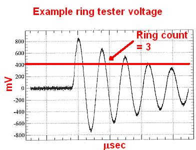
The ring tester checks for Q by applying a pulse to the DUT and then counting the number of cycles in the ringing waveform that results. More specifically, it counts the number of decaying cycles containing energy above a predetermined threshold. The number of cycles above the threshold constitutes a measure of the transformer/inductor Q. Transformers/inductors that are functioning properly will have a high Q; those containing shorted turns, not so much.

A commercially available ring tester. This one was recently available on Amazon for about $60.
It is relatively easy to find DIY circuits for ring testers, and ready-to-go units can be found online for about $60. A point to note, however, is the typical ring tester is designed to handle transformers/inductors as normally found in ordinary linear power supplies, operating in the 50-60 Hz range. That means the ring testers may not work as well for transformers/inductors designed to operate at higher frequencies. Isolation transformers for ethernet lines, for example, are typically specified for 100 kHz frequencies. Transformers used in switching supplies can be designed for frequencies into the megahertz range.

diy ring tester
A ring test circuit as devised by a Czech YouTuber.
One DIY ring tester circuit devised by a YouTuber in the Czech republic is built around an Atmel AVR ATTiny24A MPU (ATTiny24, ATTiny24V). The cathodes of a two-digit high-brightness LED display connect MPU PA port while the two common anodes connect to bits 0 and 1 of the PB port. The YouTuber multiplexes the display segments at 100 Hz. He also uses only two series resistors on the anodes (to set display current) instead of one on each segment connection that would be necessary if the digits were multiplexed. The microprocessor is clocked by an internal RC oscillator operating at 8 MHz. The whole circuit is powered by four NiMH AA cells.

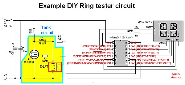
In the ring tester the YouTuber describes, the ringing is set up via an RLC series circuit where the transformer/inductor under test is the L. The C component in this arrangement must have a low dissipation factor (tan δ). The YouTuber recommends a good quality polypropylene film capacitor and cautions that a ceramic capacitor won’t work here, and a polyester cap will only work poorly.

Switching takes place via an N-channel logic MOSFET having a low on resistance (on the order of a few milliohms). The on resistance of the MOSFET actually determines the supply voltage necessary (minus the voltage drop of the MPU output) because the supply must be such that voltage applied to the MOSFET gate ensures operation in the low on state resistance region. For this reason, the YouTuber suggests a 4.8 – 5 V supply voltage, though a quick look at the MOSFET datasheet (IRLB8743) reveals the on resistance would be slightly lower with a 10-V supply. When the transistor is off (about 130 msec), the tank circuit capacitor charges through the series resistor. When the transistor turns on (about 120 msec), the low dissipation factor capacitor is in parallel with the transformer/inductor L, and damped oscillations commence. They are applied to the PA4 input of the MPU through a resistor and they are counted. The sequence repeats every 250 ms while the display gets refreshed at a frequency of about 4 Hz.

You may also like:

  • frequency you can count on
    Will 60 Hz continue to be a frequency you can…

  • June 2022 Special Edition: Test & Measurement Handbook
  • music on scopes
    Making pictures from sound on an oscilloscope
  • rental instruments
    The modern economics of renting test instruments
  • no you can't detect ghosts with a gauss meter
    No, you can’t detect ghosts with a gauss meter

Filed Under: FAQ, Featured, Meters & Testers, New Articles Tagged With: FAQ

Reader Interactions

Leave a Reply Cancel reply

You must be logged in to post a comment.

Primary Sidebar

Featured Contributions

Why engineers need IC ESD and TLP data

Verify, test, and troubleshoot 5G Wi-Fi FWA gateways

How to build and manage a top-notch test team

How to use remote sensing for DC programmable power supplies

The factors of accurate measurements

More Featured Contributions

EE TECH TOOLBOX

“ee
Tech Toolbox: 5G Technology
This Tech Toolbox covers the basics of 5G technology plus a story about how engineers designed and built a prototype DSL router mostly from old cellphone parts. Download this first 5G/wired/wireless communications Tech Toolbox to learn more!

EE TRAINING CENTER

EE Learning Center

EE ENGINEERING TRAINING DAYS

engineering
“test
EXPAND YOUR KNOWLEDGE AND STAY CONNECTED
Get the latest info on technologies, tools and strategies for EE professionals.
“bills

RSS Current EDABoard.com discussions

  • Why need use TOPmetal Stacking?
  • Monte-Carlo simulation error on ADE-XL
  • Snooping Around is All
  • Identification of a 6 pin smd chip (sto-23-6) marked E2
  • Dynacord enter protect

RSS Current Electro-Tech-Online.com Discussions

  • Does US electric code allow branching ?
  • Fun with AI and swordfish basic
  • using a RTC in SF basic
  • Faulty heat air gun (dc motor) - problem to locate fault due to Intermittent fault
  • Sump pit water alarm - Kicad 9
Search Millions of Parts from Thousands of Suppliers.

Search Now!
design fast globle

Footer

EE World Online Network

  • 5G Technology World
  • EE World Online
  • Engineers Garage
  • Analog IC Tips
  • Battery Power Tips
  • Connector Tips
  • DesignFast
  • EDA Board Forums
  • Electro Tech Online Forums
  • EV Engineering
  • Microcontroller Tips
  • Power Electronic Tips
  • Sensor Tips

Test & Measurement Tips

  • Subscribe to our newsletter
  • Advertise with us
  • Contact us
  • About us

Copyright © 2025 · WTWH Media LLC and its licensors. All rights reserved.
The material on this site may not be reproduced, distributed, transmitted, cached or otherwise used, except with the prior written permission of WTWH Media.

Privacy Policy