In general, the electrical characteristics of circuits associated with high-frequency instruments vary significantly with time. Signal sources, receivers, and interconnections drift with vibrations, cable flexing, temperature, humidity, and so forth. That’s why vector network analyzers (VNAs) are only treated as being time-invariant over short time periods (a few hours). Thus a VNA must be calibrated often if it is to make accurate measurements.
VNA calibration is the process of measuring devices and using these measurements to establish what’s called measurement reference planes. VNAs rely on calibration for accuracy even when the reference plane is at the instrument front panel connectors or at the ends of cables. Calibration also corrects imperfections which include not only the non-ideal nature of cables and probes but also the internal characteristics of the VNA itself.
A VNA calibration is analogous to subtracting the resistance of the test leads on ohm meter measurements. When the zero function is activated on an ohmmeter, the instrument stores a resistance measurement which is then subtracted from all future measurements. But where the ohmmeter’s calibration simply uses a short circuit (connecting the test leads together) to determine the resistance term in the error calculation, a VNA uses multiple calibration standards – typically open circuits, short circuits, loads, and through (thru) connections.
A VNA calibration does the same thing as the ohmmeter zero function but uses error correction containing several terms for each frequency point. The measurement system is viewed as an ideal VNA plus an adapter network modeling all of the system nonidealities: directivity of the couplers, imperfect match looking back into the reflectometer (test set ports), imperfect frequency response of the reflectometers and the transmission between ports, and the cross talk between ports.
 One-port VNA error models usually have at least six terms in them that include the measured and ideal S11 S parameter, a source match error, a reflection tracking error, and a directivity error. To solve for these error terms, the user measures the open, short, and thru standards in the calibration to generate three equations for the three unknowns. This equation system is then solved at the end of the calibration routine to yield complex values of directivity, source match, and reflection tracking errors. This provides enough information to calculate a corrected reflectivity S11.
Note that there are multiple models for VNA errors. More complicated models have more error terms. Thus a model with 12 unknown error terms requires the measurement of 12 standards in the calibration to generate 12 equations for the 12 unknowns.
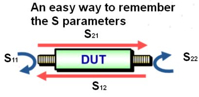
Each actual S-parameter is a function of the four measured S-parameters. Thus, the VNA must perform a forward and a reverse sweep to update each S-parameter. The calibration functions let users store measurements of standards, compute the error models, and automatically apply corrections to DUT measurements.

Corrected VNA measurements are sometimes referred to as de-embedded, and VNA calibration is also referred to as vector error correction. A large number of VNA standard sets have been developed: SOLT, LRM, LRRM, LRL, TRL, and several others. Designations like TRL refer to the standards used—SOLT for short, open, load, and thru; TRL for thru, reflection, line–and to a class of algorithm used to estimate the calibration coefficients from the measurements of the known standards.
SOLT calibration is perhaps the simplest to understand. It consists of one-port measurements using a known shorted termination, open termination and load termination. The last measurement is of a known through-connection between the two ports—usually this is accomplished by simply connecting the two test ports directly to each other. The reflection calibration measurements are used to characterize the directivity, source match and reflection tracking for each test port. The through connection permits the characterization of the forward and reverse transmission tracking as well as the load match for each port.

Many calibration algorithms such as TRL, Short-Open-Load-Reflect (SOLR), and Quick-SOLT (QSOLT) assume a constant port match. These are often referred to as eight-term error correction methods. The eight terms are directivity, reflection tracking, port match for each port and transmission tracking in both directions. There are also 12-term error correction methods which account for having a different load and source match for each port (two terms) and for crosstalk in both directions (two terms). In reality, crosstalk characterization can be applied to eight-term calibrations for a total of ten terms or can also be entirely omitted.
A point to note is that cable management is important. Cable movement during and after calibration introduces variations that calibration doesn’t characterize. But if transmission and reflection parameters vary significantly as test cables bend gently, a bad connection is likely.
In addition to SOLT, QSOLT and SOLR calibration techniques require reflection calibration for one or more of the test ports. QSOLT requires a reflection calibration on one of the ports followed by a known through-calibration. SOLR requires reflection calibration at each test port followed by an unknown through-calibration between the ports. The unknown through calibration standard is a reciprocal device (S21 = S12) with an arbitrary reflection coefficient on each port that needn’t be known. The SOLR calibration permits calibrations where the test ports may be non-insertable either because connectors don’t mate or the DUT topology doesn’t permit direct connection between the test ports.
The reflection calibration typically requires an open circuit, a short circuit, and a matched 50-Ω load. Matched loads can be broadband, having a low reflection coefficient over a wide span of frequencies, or sliding loads. Sliding loads can be expensive and are generally used only when measurements must be super accurate, as when distinguishing between a 1.01:1 VSWR and a 1.02:1 VSWR.
Inexperienced users sometimes think they can verify the validity of the calibration by measuring a through connection. If the through connection was used as a known-through standard during calibration (SOLT and QSOLT), the only information obtained is the stability and repeatability of the measurement. The SOLT and QSOLT algorithms force the measurement of the through-connection to look ideal.


Leave a Reply
You must be logged in to post a comment.