Resistivity and its inverse, conductivity, are different from the more familiar metrics, resistance and its inverse, conductance. Resistivity is applicable to types of materials.
For example, glass and carbon have specific resistivities whereas a particular carbon resistor of a given length, diameter and temperature has a specific resistance.
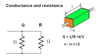
In a nutshell, resistance is defined as the property of the conductor which opposes the flow of electric current. Resistivity is defined as the resistance offered by the material per unit length for a unit cross-section. Thus in a conductor having a given resistivity, the resistance is a linear function of the length and cross-sectional area, but the resistivity is the same regardless of the dimensions.
The symbol for resistivity is ρ (Greek letter rho). The SI unit is ohm-meter. Its inverse, conductivity, is σ (Greek letter sigma). Thus σ = 1/ρ. If a one-meter conductor with leads attached to the centers of two opposite faces has a resistance of one ohm, the resistivity of the material, regardless of size and shape, is one ohm-meter.
If the cross section and physical qualities of the material being measured are uniform, and the electric field and current density are parallel and uniform, the electrical resistivity ρ is given by ω = ρ L/A, Which states that resistance is proportional to the length and inversely proportional to the cross-sectional area. This relationship is true even at high frequencies where the skin effect appears because the skin effect reduces the cross-sectional area. Because area is in the denominator, the resistance rises.
In some cases, resistivity differs according to the direction in which the measurement is take. Then it is said to be anistropic, An example is a block of wood, which splits more readily in the direction of the grain. Another example is crystalline graphite, which consists of thin sheets. Electrical current flows readily through individual sheets but across the adjacent sheets the resistivity is much greater. Current flow is not aligned with the electric field, and to quantify it, complex tensor vectors, represented in matrices, are used.
The phenomenon of conductivity in metal depends on band theory. Quantum mechanics states electrons in an atom can have only distinct energy levels which may be sufficiently close together to have a combined effect known as an energy band. In any given material or crystal lattice there may be multiple energy bands. Electrons tend to drop into lower energy states. They start at the bottom of the band and fill it to a level known as the Fermi level. Only electrons near or above the Fermi level can move freely within the band.
The high conductivity of metals arises from the existence of many energy levels close to the Fermi level, allowing many electrons to move. In insulators, in contrast, there are intervals without energy levels. The number of electrons in these materials is sufficient to fill the low-energy bands just to the boundary. Accordingly, the Fermi level falls within a bandgap. These electrons cannot move because there are no available energy states near the Fermi level.
Metals consist of a crystal lattice made up of atoms having outer shells that permit the electrons to escape and travel through the lattice. The free electrons, in the presence of external charge, then constitute the electric current.
Conductors and insulators generally are characterized in terms of their resistance. In contrast, liquids and gases are more likely to be measured for their conductivity. Liquids have charge carriers that are ions: electrically imbalanced atoms or molecules free to drift. The degree of electrical conductivity of any liquid thus depends on the ion density, how many ions freely exist per unit volume of liquid. Applying a voltage across a liquid solution causes negative ions to drift toward the positive pole and positive ions to drift toward the negative pole. Thus negative ions are sometimes called anions (attracted to the anode) while positive ions are cations (attracted to the cathode).
Similarly for gases, ions are the charge carriers. However, gases at room temperature have practically no ionic activity. A gas must be superheated into a plasma to get enough ions to support an electric current.
Pure water is a poor conductor of electricity. Any substance dissolved in water that boosts electrical conductivity is called an electrolyte. Higher conductivity comes from the molecules of the electrolyte separating into positive and negative ions, which can then serve as electrical charge carriers. If the electrolyte is an ionically-bonded compound (like table salt), the ions forming that compound naturally separate in solution through what’s called dissociation. If the electrolyte is a covalently-bonded compound (hydrogen chloride for example), the separation of those molecules into positive and negative ions is termed ionization.
Ionic impurities added to water (such as salts and metals) immediately dissociate and may act as charge carriers. Thus, measurements of water electrical conductivity are measuring its concentration of ionic impurities. Consequently, conductivity can serve as a measure of water purity. That said, the conductivity of a liquid solution says nothing about what ions are present in the solution.
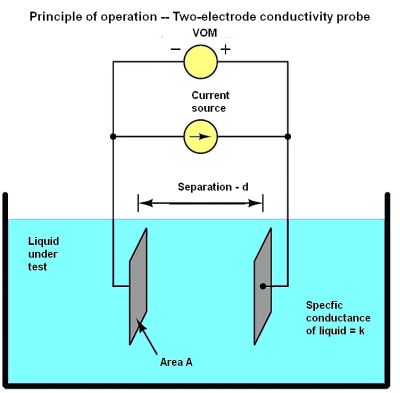
One way to measure the electrical conductivity of a liquid solution is by passing an electric current through it. The simplest conductivity sensor (sometimes called a conductivity cell) consists of two metal electrodes in the solution, connected to a circuit designed to measure conductance. Unfortunately, the measurement depends as much on the area and separation distance of the plates as on the ionic activity of the liquid solution.
The equation for conductance G in this case is G = k(A/d) where k = specific conductance (conductivity) of the liquid, S/cm; A = plate area, cm2; and d = area of each electrode, cm. Thus k = (Gd)/A.
To quantify the plate geometry for any particular cell, manufacturers typically express the fraction d/A as a single value called the cell constant, symbolized by θ and expressed in inverse centimeters, cm-1. Then k = Gθ.
Two-electrode conductivity cells are impractical in real applications because mineral and metal ions are attracted to the electrodes tend to eventually foul them. Use of ac rather than dc excitation can minimize this “electroplating” action, but fouling still arises. The resulting conductive barriers formed by ions bonded to the electrode surfaces will create calibration errors and make the liquid appear less conductive than it really is.
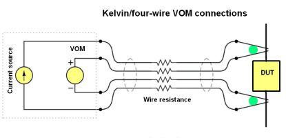
Kelvin or four-wire resistance-measurements eliminate fouling problems of two-electrode conductivity probes. As a quick review, the four-wire technique connects the resistance under test to the measuring instrument via four conductors. It is generally used when there is a substantial length of test lead between the DUT and the test instrument. Only the outer two conductors carry substantial current. The inner two conductors connecting the VOM to the test specimen carry negligible current (because of the VOM’s extremely high input impedance) and thus drop negligible voltage along their lengths. Voltage dropped across the current-carrying (outer) wires is irrelevant, because the VOM never detects that voltage drop. Because the voltmeter only measures voltage dropped across the specimen and not the test resistance plus wiring resistance, the resulting resistance measurement is more accurate than in the two-wire case.
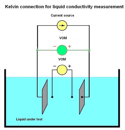
For conductivity measurements, it is not wire resistance that must be canceled out, but rather the added resistance caused by fouling of the electrodes. Use of four electrodes rather than two allows measurement of voltage only dropped across a length of liquid solution and completely ignores the resistive effects of electrode fouling. Any fouling on the two inner electrodes has no impact because these inner electrodes carry negligible current. With little or no current through them, there will be negligible voltage across any resistive coating, allowing the VOM to still register the true voltage across the liquid solution.
Given the solution conductivity is k = Gθ and conductance G is defined as the ratio of current to voltage, then combining the two equations gives k = Iθ/V. Some conductivity instruments employ a second VOM to measure the voltage dropped between the “excitation” electrodes, to indicate electrode fouling. Any electrode fouling will cause this secondary voltage measurement to disproportionately exceed the first, thus indicating when the probes need cleaning.
An entirely different design of conductivity cell called electrodeless uses electromagnetic induction rather than direct electrical contact to detect the conductivity of the liquid. This approach has the advantage of virtual immunity to fouling because there is no direct electrical contact between the measurement circuit and the liquid. This cell uses two toroidal inductors, one to induce an ac voltage in the liquid, the other to measure the strength of the resulting current through the solution.
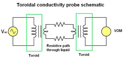
The underlying principle of this instrument is that a primary coil energized by ac induces an electric current that passes through the sample liquid. This current, in turn, induces a measurable voltage in a secondary coil. The magnetic fields of toroids are largely contained in the magnetic material itself, so there will be negligible mutual inductance between the two wire coils. The only means of inducing a voltage in the secondary coil is if ac current passes through the center of that coil, through the liquid itself.
If the liquid is non-conductive, the secondary coil will see no induced voltage. The more conductive the liquid, the more current passing through the center of both coils (through the liquid). Secondary coil voltage therefore is directly proportional to liquid conductivity.
One problem: Toroidal cells are too insensitive for conductivity measurements in high-purity applications. Examples include boiler feedwater treatment and ultra-pure water treatment for pharmaceutical and semiconductor manufacturing.


Leave a Reply
You must be logged in to post a comment.