You often hear it said that motors and generators are the same thing–put electrical power into a motor and it generates mechanical torque. Turn the shaft of an electric motor and it generates electrical power. This statement is true theoretically. But motors and generators have different architectures. So you might wonder why there’s a difference. It is easy to understand the reason by examining the makeup of an alternator as used on a vehicle with an internal combustion engine. (Electric vehicles have generators too, but they are generally used on each wheel for regenerative braking and are a bit more exotic than ordinary vehicle alternators.) And an examination of alternator operation reveals why these devices output sine waves rather than some other kind of waveform.
The shaft of the typical alternator connects to the engine crankshaft via a belt and pulley. The running engine turns the rotating part of the alternator, naturally enough called the rotor, to generate ac. Because the vehicle uses dc and not ac, rectifier diodes sit on the alternator to perform the conversion. A point to note is that the output voltage of the alternator varies with the speed of the engine. Consequently, the alternator also contains a regulator to limit the alternator output at high speed. This is the first important difference between an alternator and an electric motor: Ordinary ac motors run at a constant speed dictated by the ac line frequency whereas alternators run at the speed of whatever is driving them. (We are ignoring variable-speed ac drives here for simplicity.) So alternators need regulators to limit their output. And the generated output is the same frequency of the spinning rotor. So when alternators or generators feed power into an ac system, they must have a way of precisely synchronizing their output frequency with that of the system they are feeding.
There are generally three connections to a vehicle alternator: one for the output which charges the battery, a second that allows the regulator to sense the generated voltage, and third connected to the ignition to provides the initial power to the starter motor. The circuit is completed when electricity flows back through the car frame to the negative battery terminal.
The stationary part of the alternator is, naturally enough, called the stator. It consists of numerous laminated sheets having a pattern of slots around the inner edge. There are typically three separate sets of copper wires wound between these slots to form coils surrounding the rotor. One end of each coil is connected together to form a neutral point, forming what’s called a star configuration. Each coil set produces a single phase of ac. The other end of each coil connects to the rectifier.
The rotor of the alternator contains a coil of wire wound around an iron core. The rotor shaft also holds two slip rings. The slip rings are connected to opposite ends of the rotor coil. Making contact with the slip rings are spring-loaded carbon blocks called brushes. The spring loads push the brushes toward the slip rings so they make electrical contact as the alternator rotor turns.
The car battery initially provides electricity to the rotor coil via the brushes, forming an electromagnet. As the electricity passes through the coil, it generates an electromagnetic field. Two iron claws typically sit at either end of the coil and interlock with each other to boost the magnetic field strength. One end becomes the north pole, the other the south pole. When the engine turns the alternator shaft, the electromagnet rotates past the stator coils to generate a current. Once the alternator is generating electricity, it can power the electromagnet by itself via a diode trio which converts the three-phase ac into dc.
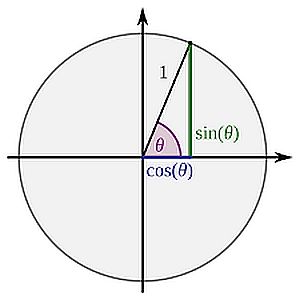
The sine wave output of the alternator can be explained this way: Suppose the electromagnet starts out between two stator coils. There is no current generated, but as the magnet starts to rotate, the strongest part of the magnetic field gets closer and closer to a coil. The coil experiences a magnetic field having a changing intensity which causes current to flow up to some maximum level. Then the magnet starts to move away from the coil, so the magnetic field begins to drop, and so does the induced current until it reaches zero. Now the opposite end of the electromagnet begins to get closer to the coil. This action causes current flow in the opposite direction, again to a maximum level and then dropping back to zero. A plot of this current on a chart yields a sine wave with the current flowing in the positive and then negative regions.
Placement of another stator coil 120° from the first phase will generate a second phase because the coil is at a different angle, so it will experience the change in intensity of the magnetic field at a different time. Ditto for a third phase. Instead of having three separate coils and six wires, the ends of the stator coils connect together. The current will then flow freely between each coil as current changes direction.
That brings us to the voltage regulator. Recall that varying the voltage to an electromagnet varies the resulting electromagnetic field strength. And varying the electromagnetic field strength varies the voltage and current generated in the stator coil. So the regulator controls the amount of alternator output by regulating the current through the rotor coils as they spin. It generally does so via a transistor. By measuring the output of the alternator and then varying the open and close times of the transistor switch, it controls the current flow through the rotor coil and the strength of the electromagnet in a manner that lets the alternator maintain a constant output.
Finally, you might wonder how ac generators handle the variable frequency output that results from a rotor spinning at a non-constant speed. If we are talking about small generators and small differences with the ac line frequency, there is generally no problem; a small generator plugged into the grid will generally synchronize itself to the grid frequency if its output frequency is close to that of the mains. If the generator output is of a frequency wildly different from that of the mains, the usual approach is to add a synchronous inverter. This device continuously samples the utility ac and synthesizes an output to match, copying the utility waveform with regard to voltage, frequency and phase angle.


Leave a Reply
You must be logged in to post a comment.