To engineers schooled in modern motor control methods, it may be hard to grasp why three-speed fans designed to move air around in a room can be inexpensive. After all, these fans are powered by as motors, and the go-to method for changing the speed of industrial ac motors is via variable-frequency drives. VFDs work well for industrial pumps and air handlers but are too pricey to be used for inexpensive consumer fans. So how do ac fans that only cost a few dollars manage to change their speed?
The answer lies in the motor windings and in the basic equation for ac motor speed. There are two main ways an inexpensive fan can be given a capacity for multiple speeds. We’ll start with the simplest way, which is compatible with the simplest ac motor, the shaded pole motor.
 The shaded-pole motor consists of a squirrel-cage rotor—a cylinder of steel laminations with aluminum or copper conductors embedded in its surface—and a stator winding. The term shaded pole comes from the use of a separate small winding, called a shading coil, in the stator. Electromagnets in the stator are formed by coils around steel laminations. The shading coil is wound around a small section of the laminations. When ac is supplied to the main winding, a portion of the resulting magnetic flux links to the shading coil. This induces a current in the shading coil which behaves like the secondary of a transformer. The induced current, in turn, produces its own (weak) magnetic flux which lags the magnetic flux in the main portion of the stator. Consequently, there is a time and space displacement between the two fluxes. This time and space displacement sets up the conditions for a rotating (or shifting) magnetic field. The rotating magnetic field is what starts and keeps the rotor turning.
Shaded pole motors are inexpensive because they have a pretty simple construction. The starting torque of shaded motors is low, so they are pretty much confined to use in fans or other loads that are easily started. They may have multiple taps near one electrical end of the winding, which provides variable speed and power by selection of one tap at a time, as in ceiling fans.
Moreover, they are compatible with ordinary triac light dimmer switches, which often are used with fans. They are built in power sizes up to about 1⁄4 horsepower (190 W) output. Above 1⁄3 horsepower (250 W), other motor architectures offer better qualities.
In a nutshell, shaded pole motors can run at different speeds by means of reducing the winding voltage. This is equivalent to saying they run at lower speeds by reducing the power coupled to the rotor either by tapping off the stator winding at different points or by reducing the voltage applied to the stator winding via an ordinary triac dimmer switch. This approach works because the torque developed is proportional to the square of the supply voltage while the current is proportional to the voltage. Hence, to reduce the motor speed for the same value of the same current, we reduce the value of the voltage. Consequently, the motor develops less torque. Thus control methods that reduce the stator voltage somehow work for applications where the load torque drops with the speed. Fans are a perfect example.
However, there are ways of reducing ac motor speed that don’t reduce motor torque and that don’t require a VFD. We refer to the equation that spells out how motor speed is determined:

where Ns is synchronous speed, rpm; Nr is actually speed; f is line frequency, Hz; s is the amount of slip, the relative speed between the rotating magnetic flux and rotor expressed in terms of per unit synchronous speed, a dimensionless quantity.; and P is the number of motor poles. A point to note is that the actual motor speed depends on the line frequency–which is what changes in the case of a VFD–but also on the number of poles. Thus increasing the number of poles reduces the motor speed. That is precisely what goes on in the case of consequent-pole motors.
In a motor with consequent poles, each stator winding is divided into two coils and the two ending terminals of each coil group is brought out. The terminals of each coil group is swapped to change the number of stator poles. Unfortunately, that explanation is about as clear as mud. We’ve found that a real understanding of the technique, and where the idea of the consequent poles arise, only comes from examining graphic depictions of the situation. The clearest depictions we’ve found come from YouTuber garnermarcify. We’ll use images from a couple of garnermarcify videos to explain the concept.
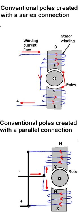
First consider how a conventional pole is formed with a stator coil. As long as the stator windings are such that stator current flows in the same direction around each pole piece, we will create one north and one south magnetic pole opposite the rotor. Depending on whether the windings on the pole piece go in the clockwise or counterclockwise direction, this can be done with either a series or parallel connection.
To create consequent poles, the connections to the armature winding change slightly. Current flows through windings in a direction that creates poles facing the rotor that have he same polarity–either two north poles or two south poles. The two like poles, of course, repel each other. But in so doing, they also create two additional “consequent” poles of the opposite polarity in the armature region. The consequent moniker arises because the additional poles are created as a consequence of the two like poles.

Referring back to the equation for motor speed, recall that increasing the number of poles reduces the motor rpm. In practice, the winding connections necessary for creation of the consequent poles are typically implemented by a motor starter. Though the configuration described here will result in a two-speed motor, it’s also possible to add an additional winding connection to implement a three-speed consequent pole speed control. Finally, one benefit of the consequent pole speed control is that it does not incur a loss of horsepower, unlike control via triacs and tapping off part of the armature winding.
There is another technique called pole-amplitude modulation (PAM) that somewhat resembles consequent pole speed control. The benefit of the pole-amplitude method is that can implement changes in motor speed other than the 2:1 speed ratio ordinarily realized in consequent pole setups, though the motor must be designed specifically for PAM.
The fundamentals of PAM come out of the equations defining the rotating magneto-motive force wave distribution in the air gap between the rotor and stator. There is a separate equation describing the force for each phase of the motor, and the equation is a sinusoid that includes terms for the number of pole pairs and the mechanical angle (the angle of the rotor shaft vs the stator). Now suppose there is a modulating MMF wave for each phase and that the modulating waves are displaced from each other by a fixed amount (2π/3 radians for three-phase motor windings). If k = the number of modulating cycles in one complete rotor rotation and p = the number of motor poles, mathematically it can be shown that the result of the modulation is two sets of MMFs with (p-k) and (p+k) poles. The two sets of poles produce torques in opposite directions.
To get a steady torque in one direction, one of the pole pairs must be suppressed. There are two ways to realize the effect, coil inversion and coil inversion plus omission. Both approaches divide the winding of each phase into two parts. In coil inversion the current through the second half of the winding in each phase in reversed, somewhat analogously to that of consequent pole speed control. As you would expect in a consequent pole speed control, this reverses the polarities of half the poles. In coil inversion and omission, half the winding is left de-energized (omitted) while the remaining portion is reversed. This technique is useful for getting speed control other than in a 2:1 ratio as, say, by reducing the number of effective poles from eight to six.
By judiciously choosing series or parallel connections to the coil groups of each motor phase, and by selecting a star or delta connection between the phases, the speed can be reduced while maintaining a constant torque or motor power, or a variable torque. But typically PAM motors are three-phase devices employed in pumps, blowers, and fans.

Leave a Reply
You must be logged in to post a comment.