Though 5G is a promising technology, astronomers and Earth scientists are worried that 5G frequencies could interfere with the scientific use of previously quiet parts of the electromagnetic spectrum.
The Federal Communications Commission recently came out with rules allowing experimental devices to use frequency bands between 95 GHz and 3 THz. Scientists see several problems with this idea. For one thing, they say the FCC has not considered the interference that could arise with sensitive celestial and terrestrial observations at various frequencies above 95 GHz. Additionally, NASA and the National Oceanic and Atmospheric Administration have said the opening of a 24 GHz band to new 5G equipment could degrade efforts at forecasting weather. And the American Geophysical Union and American Meteorological Society both have problems with an FCC rule requiring NOAA to share the 1.675–1.680 GHz band now used to transmit data from geosynchronous weather satellites.
To understand the concerns, it is helpful to review how radio telescopes operate and the frequencies involved in some of the phenomena they examine. The first radio telescope was built quite by accident in 1932 by Karl Guthe Jansky, a scientist working for Bell Telephone Labs. The intention was to pinpoint sources of static that might interfere with radio reception in the telephone network. He came across a persistent electromagnetic hiss that emanated from a fixed point on the celestial sphere. He was in fact aiming the antenna at the center, the densest part, of the Milky Way.
Five years later, an amateur radio operator built a 30-ft parabolic dish antenna in his backyard in Illinois and commenced a methodical mapping of extraterrestrial sources emitting very high frequency waves.
Most radio telescopes consist of parabolic reflectors that focus the energy at one point whereupon it travels via coaxial cable or, if the frequency is too high for that, via a waveguide to the location of the frequency converter. At that point the signal mixes with a lower frequency that produces a down-converted signal that can move the required distance through coax to its next destination, typically a high-gain amplifier. Subsequent blocks are signal processing, signal detection and post-detection processing. The end result may be viewed by means of a spectrum analyzer or as a conventional image on a monitor, or it can be printed.
One phenomenon radio telescopes are now used to observe are neutron stars, which occasionally generate a giant pulse. The Arecibo radio telescope in Puerto Rica has noticed pulses from neutron stars lasting two nanoseconds. The necessary receiver bandwidth is on the order of several gigahertz.
The lengths to which radio telescope installations must go to gather super faint signals is exemplified by the Arcminute Micro kelvin Imager (AMI) in the U.K. It consists of two separately correlated arrays of receivers operating in 12 to 18 GHz band. One part of the array consists of ten 3.7-m parabolic dishes. They can resolve angular scales of 2 to 16 arc minutes. The small array links to a large array formed by eight 12.7-m dishes including two offset dishes to create a north-south baseline to cover angular scales of 0.5-5 arc minutes.
The small array detects shadows that galaxy clusters have imprinted on the cosmic RF background. The large array provides corrections for contaminating radio sources. The overall bandwidth is six gigahertz divided into eight broadband 750-MHz channels. The point of AMI is to see galaxy clusters that are tough to detect optically such as those hidden behind cosmic dust clouds.
Another array set up in Chile’s Atacama Desert has 66 steerable 12 and 17-m parabolic reflectors. The reflector electronics is connected together via fiber connections having tolerances of less than ten microns. The array excels at studying the shifted spectral lines of water, carbon dioxide, oxygen and nitrogen.
The use of fiber links between antenna sites, rather than radio links, boosts the bandwidth of the array as well as the sensitivity. The antenna site link together because the array of dishes forms an interferometer. When used together, the dishes act as a single dish with a diameter of about the distance between the farthest dishes.
 You can get a feel for the instrumentation behind a typical radio telescope by examining the makeup of a relatively new installation, the Australia SKA Pathfinder.
The typical radio telescope antenna uses a parabolic receiving surface that forces incoming RF to bounce up to a single focus point. The dish bounces numerous RF wavelengths to the focal point. To observe specific wavelength ranges, the focal point generally contains several feed horns each having dimensions the same size as a critical wavelength of interest. Each feedhorn is basically a resonator for a specific frequency range that amplifies the incoming RF. The feedhorn output typically goes to a supercooled receiver and is then digitized.
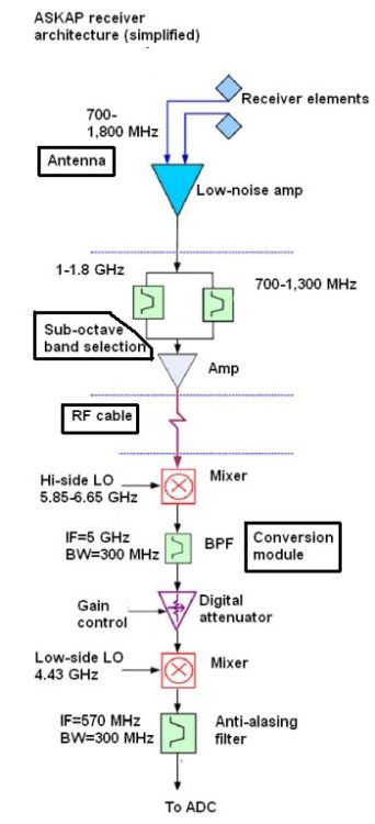
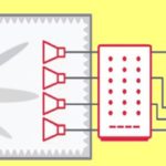
The ASKAP installation is a bit different in that there are no feedhorns at the antenna foci. Instead, there is what’s called a phased-array feed (PAF) followed by low-noise amplifiers. Researchers describe the PAF as consisting of a checkerboard array of square conducting patches on an electrically thin dielectric sheet built on a printed circuit board/foam/ground plane sandwich. The PAF produces electrically balanced signals that go to low-noise amplifiers, and the amplifier/PAF interface apparently involves tricky impedance relationships that must be carefully optimized.
 A two-conductor transmission line connects each patch to low-noise amplifiers via holes in the ground plane. Each ten-element square PAF will have 192 individual receiving elements, each connected to a low-noise amplifier immediately adjacent to it.
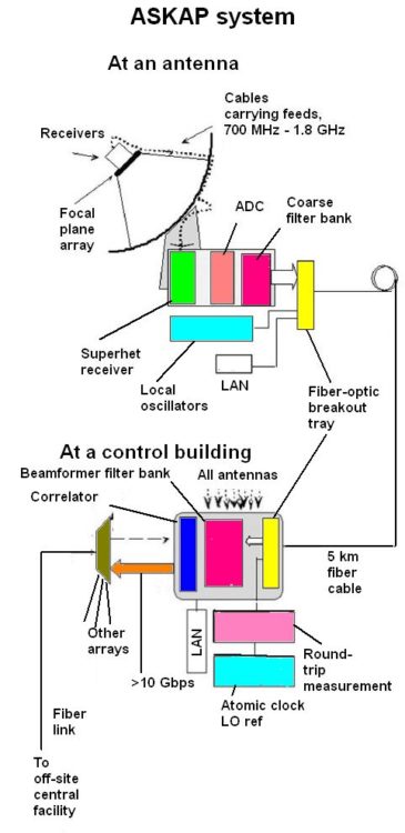
The output goes to a superheterodyne frequency conversion system and digitizer. The location of the conversion system is a tradeoff: The nearer the ADCs are to the PAF elements, the greater the likelihood of self-generated RFI pickup from the digitizing hardware; but the further the ADC is from the PAF, the more difficult it becomes to preserve phase stability, amplitude stability, and the dynamic range of the
RF signal.
Coax cable brings signals from the antenna focus to the equalizer, frequency conversion system and ADCs in the pedestal of the antenna. The frequency conversion system also filters the signals before sampling so undesired signals, which could be aliased or folded into the received band, get suppressed. The final 300-MHz-wide IF (420–720 MHz) is digitized at a 768 Msamples/sec rate.
Data from each antenna streams back to a central building at about a 2 Tbps rate via a fiber-optic network. The central building contains a digital beamformer, correlator, tied-array beamformer, and single-pixel back-ends (e.g., pulsar processors) all sitting in a screen room. Raw correlated image data then is sent back over a fiber-optic link to a computing facility about 350 km away where the gridded, calibrated images are archived.
Worries are that 5G interference could render telescopes like the ASKAP system inoperable. In comments to the FCC about the proposed 5G spectrum, the National Academies Committee on Radio Frequencies (CORF) highlighted the importance of passive bands above 95 gigahertz and urged that certain bands be completely cordoned off.
“Notably, the emissions that radio astronomers receive are extremely weak—a radio telescope receives less than 1% of one-billionth of one-billionth of a watt (10-20 W) from a typical cosmic object. Because radio astronomy receivers are designed to pick up such remarkably weak signals, radio observatories are particularly vulnerable to interference from in-band emissions, spurious and out-of-band emissions from licensed and unlicensed users of neighboring bands, and emissions that produce harmonic signals in the RAS bands, even if those human-made emissions are weak and distant,” CORF wrote.


Leave a Reply
You must be logged in to post a comment.