X-rays occupy a band within the electromagnetic spectrum higher in frequency (between 0.10 and 10 nm wavelength) than ultraviolet radiation and lower in frequency than gamma rays (less than 10 pm wavelength). At such a high frequency, the amount of energy they carry is awesome. They pass with minimal loss through most substances and their ionizing potential is substantial.

X-rays today are generated from X-ray vacuum tubes consisting of an anode and a cathode, heated by an adjacent energized tungsten filament. Electrons, carrying a negative charge, boil out of the hot cathode (operating in the 40-kV range) and fly toward the positive-biased anode. Raising the filament and cathode temperature increases the electron current, determining the intensity of the final X-ray beam. Raising the bias determines the energy of incident electrons.
An electron, sufficiently energized, striking a metal object causes it to emit an X-ray photon. The voltage difference between the cathode and anode determines the kinetic energy of the electrons striking the anode and in turn the kinetic energy or penetrating power of the emitted X-ray photon.
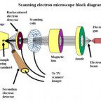
Thus, the X-ray tube resembles an oscilloscope or TV cathode-ray tube except that rather than writing a waveform trace or scanning an image on a phosphor-coated screen, the electrons strike an anode, which emits X-photons that are directed by the geometry of the anode to pass effortlessly through the glass wall at a prescribed location in the form of a collimated beam (not coherent as in a laser).
That said, readers might wonder whether LEDs may eventually replace tubes for generating X-rays. That doesn’t look likely. It only recently became practical for LEDs to generate high UV light (around 270 nm). The wavelength of LED light depends on the energy band gap of the semiconductors used. There doesn’t seem to be any semiconductor with a band gap even in the right ballpark to produce an output at 10 nm.
Electrons are inelastic. When they enter the electrical field of an atomic nucleus, they abruptly decelerate at a high rate. Being virtually massless, they can do that. These electrons are deflected and a photon is emitted. Because of its high energy, it falls within the X-ray band of the electromagnetic spectrum. This type of radiation is known as bremsstrahlung or “braking radiation”.

The first X-ray detector was simply a photographic film. A negative would darken when exposed to the invisible X-rays. There are currently several types of X-ray detectors in use:
• Scintillation detectors use Compton scattering of X-rays inside a transparent crystal to detect X-rays. These rays strike electrons in the crystal, freeing them so that they strike other atoms, emitting light, which can be detected by a photomultiplier tube.
• In proportional counters, X-radiation is beamed through a gas-filled cylinder, in which it ionizes atoms, creating free electrons. A strongly positive biased electrode attracts these free negatively-charged electrons, and additional free electrons are activated, creating a measurable electrical pulse.
• In a microchannel plate, again there is an avalanche of electrons, which produce a pulse on the output electrode.
• In a charge-coupled device (CCD) operating in the photon-counting mode, an X-ray will cause the release of a great many electrons, and quantifying them can provide information pertaining to the energy of the X-radiation.

X-ray imaging is highly successful in diagnosing skeletal pathologies because bones have a high calcium content, which, because of its high atomic number, absorbs X-rays so that the bones contrast with respect to the surrounding soft tissue. Fractures can be seen and the bones can be manipulated so that they will fit together and fuse correctly. Some soft tissue pathologies can be readily imaged and diagnosed, notably tumors, pneumonia and pulmonary edema. Brain and muscle imaging are more challenging.
Low energy, so-called “soft” X-rays have less penetrating ability. Since higher intensities and longer exposures are required to achieve comparable results, soft X-ray usage is actually more hazardous than hard X-ray imaging.
Soft X-rays are undesirable in diagnosing and treating pathologies. They are absorbed by living tissue, increasing the dosage without contributing to the image. As a remedy, a piece of aluminum sheet metal known as an X-ray filter can be situated across an X-ray tube window, where it absorbs the lower frequency component of the total radiation. This process is known as “hardening”.
X-ray photons are considered a form of ionizing radiation, which is potentially hazardous because of its ability to ionize atoms and break molecular bonds, killing animal and plant tissue. Sufficient exposure to high levels of ionizing radiation causes radiation sickness. Medical imaging involves low-level, short-duration exposure. Radiation therapy, consisting of longer exposure to higher levels of ionizing radiation has been successful in destroying malignant cancer cells. However this procedure is not without risk and long-term success is not a certainty, but in many instances, the benefits outweigh the risks.
Wavelengths of hard X-rays are smaller than many atoms, and for this reason, they are useful in the field of X-ray crystallography, in which the location and orientation of atoms within matter in its crystalline form can be determined. Due to its faceted nature, a crystal diffracts an X-ray beam in multiple directions, and the patterns of the divergent rays convey information regarding the crystal’s atomic layout and chemical bonds. In this investigation, semiconductors are objects of great interest.
When X-radiation is applied to a crystal, two-dimensional images are obtained from the diffraction pattern produced. In one more iteration of the Fourier Transform, these two-dimensional diagrams can be converted to three-dimensional representations, which are relevant in many areas of research such as size of atoms and chemical bonds, and distinguishing features of various minerals and alloys. Additionally, there are applications in organic chemistry.
There is not a precise boundary within the frequency spectrum between X-rays and gamma rays. The distinguishing difference is that X-rays are produced when electrons of sufficient energy strike a conductive object, which responds by emitting an X-ray photon. Gamma rays, in contrast, are emitted by the atomic nucleus, and therefore have higher energy, higher frequency and shorter wavelength.
Neither X-rays nor gamma rays are able to penetrate earth’s upper atmosphere. Gamma rays are even more hazardous than X-rays. On earth, gamma rays are a byproduct of nuclear fission, neutral pion decay, and nuclear fusion as well as natural lightning storms or powerful lightning arcs created artificially. They have greater penetrating power than alpha and beta rays, which hence are more ionizing. Also, unlike alpha and beta rays, they are deflected to a lesser degree by a magnetic field, because they have no charge. The fact that, like X-rays, they are a form of electromagnetic radiation is verified by the observation that they are reflected from crystal surfaces.


I am really interested in what you have as testing go’s thank you.