• Skip to primary navigation
  • Skip to main content
  • Skip to primary sidebar
  • Skip to footer
  • Advertise
  • Subscribe

Test & Measurement Tips

Oscilloscopes, electronics engineering industry news, how-to EE articles and electronics resources

  • Oscilloscopes
    • Analog Oscilloscope
    • Digital Oscilloscope
    • Handheld Oscilloscope
    • Mixed-signal Oscilloscope
    • PC-based Oscilloscopes – PCO
  • Design
  • Calibration
  • Meters & Testers
  • Test Equipment
  • Learn
    • eBooks/Tech Tips
    • FAQs
    • EE Training Days
    • Learning Center
    • Tech Toolboxes
    • Webinars & Digital Events
  • Video
    • EE Videos
    • Teardown Videos
  • Resources
    • Design Guide Library
    • Digital Issues
    • Engineering Diversity & Inclusion
    • Leap Awards
    • White Papers
  • Subscribe
You are here: Home / Oscilloscopes / Digital Oscilloscope / GW Instek GDS-1000-U Series of Digital Oscilloscope

GW Instek GDS-1000-U Series of Digital Oscilloscope

July 14, 2011 By Test and Measurement Editor Leave a Comment

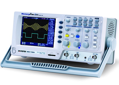
GW Instek (www.gwinstek.com) has unveiled the GDS-1000-U Series of digital oscilloscopes. These dual channel oscilloscopes offer bandwidth ranging from 50 MHz to 100 MHz and large 5.7 color TFT LCD displays. With a real-time sampling rate of 250 MSa/s, 4,000 point record length, dual sampling modes and an ET sampling rate of 25 GSa/s, these new oscilloscopes offer a remarkable balance of performance between sampling speed and memory length.

The series is specifically design to meet even the most demanding engineering budgets and requirements. It also offers other significant features, such as ergonomic design, user-friendly menu tree operations, USB host for PC connectivity, compact size and USB device port support.

Its front USB host port enhances the product’s data storage capability since large amount of data, including waveform, screenshots and panel setup, can be conveniently stored into a flash disk A, while its rear USB device port facilitates transfers of waveform raw data and screen image to the PC via remote control.

The series’ data logger allows users to store waveform data in a USB flash disk while monitoring the input signals, effectively saving the time and effort of the users spent on tracking signals manually.

The memory of the oscilloscopes can save a total of 15 waveforms. Two live waveforms and two saved reference waveforms can be simultaneously compared on the screen. Its Measure key press enables users to view all voltage and signal time related measurements on the screen.

The oscilloscopes also feature 19 auto measurement functions and several acquisition modes to help users accurately measure the waveform’s characteristics. Its advanced auto-set function allows the oscilloscope to automatically capture and quickly display waveforms, while its arithmetic and FFT functions keeps users aware of updated measurement results.
Filed Under: Digital Oscilloscope, Oscilloscopes Tagged With: digital oscilloscope, GW instek, oscilloscopes

Reader Interactions

Leave a Reply Cancel reply

You must be logged in to post a comment.

Primary Sidebar

Featured Contributions

Why engineers need IC ESD and TLP data

Verify, test, and troubleshoot 5G Wi-Fi FWA gateways

How to build and manage a top-notch test team

How to use remote sensing for DC programmable power supplies

The factors of accurate measurements

More Featured Contributions

EE TECH TOOLBOX

“ee
Tech Toolbox: 5G Technology
This Tech Toolbox covers the basics of 5G technology plus a story about how engineers designed and built a prototype DSL router mostly from old cellphone parts. Download this first 5G/wired/wireless communications Tech Toolbox to learn more!

EE TRAINING CENTER

EE Learning Center

EE ENGINEERING TRAINING DAYS

engineering
“test
EXPAND YOUR KNOWLEDGE AND STAY CONNECTED
Get the latest info on technologies, tools and strategies for EE professionals.
“bills

RSS Current EDABoard.com discussions

  • Why need use TOPmetal Stacking?
  • Monte-Carlo simulation error on ADE-XL
  • Snooping Around is All
  • Identification of a 6 pin smd chip (sto-23-6) marked E2
  • Dynacord enter protect

RSS Current Electro-Tech-Online.com Discussions

  • Does US electric code allow branching ?
  • Fun with AI and swordfish basic
  • using a RTC in SF basic
  • Faulty heat air gun (dc motor) - problem to locate fault due to Intermittent fault
  • Sump pit water alarm - Kicad 9
Search Millions of Parts from Thousands of Suppliers.

Search Now!
design fast globle

Footer

EE World Online Network

  • 5G Technology World
  • EE World Online
  • Engineers Garage
  • Analog IC Tips
  • Battery Power Tips
  • Connector Tips
  • DesignFast
  • EDA Board Forums
  • Electro Tech Online Forums
  • EV Engineering
  • Microcontroller Tips
  • Power Electronic Tips
  • Sensor Tips

Test & Measurement Tips

  • Subscribe to our newsletter
  • Advertise with us
  • Contact us
  • About us

Copyright © 2025 · WTWH Media LLC and its licensors. All rights reserved.
The material on this site may not be reproduced, distributed, transmitted, cached or otherwise used, except with the prior written permission of WTWH Media.

Privacy Policy