The oscilloscope is essentially an auto-ranging voltmeter. But in examining electrical equipment, it’s often useful to take current measurements. A current measurement may convey a more realistic picture of what is going on. When there is excessive current, the consequence is high temperature rise, which can quickly damage the electrical equipment and create a hazard.
Kirchhoff’s Current Law provides valuable insights. Kirchhoff’s First Law states that the algebraic sum of currents flowing in a conductor network terminating at any given point is zero. This insight is indispensible in tracing complex circuit paths. The basic implication is that current does not go away. It can drive machinery such as a rotary motor, move an actuator, or power a light bulb or speaker. It may be stored in a chemical battery, capacitor or magnetic field. But it does not vanish, and accordingly it is traceable and provides meaningful insights. Engineers express electrical energy loss as I2R heat dissipation. It moves outside the enclosure but it does not cease to exist.
Current measurements using an oscilloscope generally use a current probe. It works the same as an electrician’s clamp-on ammeter, where heavy-duty jaws clamp around the conductor in which the current flow is to be measured.
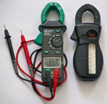
A clamp-on ammeter may have a digital or analog readout. As a quick review, the clamp-on ammeter relies on the fact that a magnetic field forms when current flows through a conductor. This magnetic field induces magnetic flux in the low-reluctance jaws, creating voltage appearing at the readout, which is remarkably stable. It doesn’t matter whether the conductor is exactly centered in the jaws or if it passes through at an angle.
An oscilloscope current probe works in the same way. It is smaller, its size appropriate for clamping around the small conductors attached to a circuit board or to discrete devices that are part of electronic equipment under investigation.
However, because an oscilloscope current probe sells for about $1,000, budget-conscious engineers may investigate the idea of making oscilloscope current measurements using an existing voltage probe. This is a realistic alternative but it may be problematic.
If the ground reference lead of a bench-type oscilloscope touches a wire or terminal referenced to and floating above ground potential, there will be a low-impedance short circuit with sparks and smoke. This is not an issue when the probe tip touches metal that is so energized. It is the return lead that is at risk. In making any of the voltage measurements described below where the object is to ascertain current flow, a hazardous fault circuit can result, so you have to be aware of the bad configuration.
The entire issue can be easily circumvented by using a hand-held, battery-powered oscilloscope. This instrument typically has two or four analog inputs that are isolated from ground, even when the battery is being charged from an ac receptacle. The ground return leads of probes connected to these channels are generally insulated from each other as well, so there is no danger from low-impedance short circuits. Many users prefer the portable instrument for this reason and also because it is easy to move around, less expensive than a premium bench-type oscilloscope, and does not need an ac receptacle at the site.
Voltage measurements can be used to calculate current flow through a device or through any portion of a circuit. From Ohm’s Law:
E = I x R
Where E = electromotive force in volts
I = current in amps
R = resistance in ohms
Solving for I:
I = E/R
First, then, it is necessary to know R. It can be determined by means of a high-impedance ohmmeter as incorporated in an ordinary multimeter. It will not load ordinary circuits or devices because of the high impedance. Still, it may not provide a true picture of the circuit parameter of interest. Most multimeters output around 3 Vdc at the probes. While this will not harm ordinary circuits or devices, it may not yield a realistic resistance reading under actual circuit conditions because the resistance can change as the applied voltage varies.
Second, overall impedance — as opposed to dc resistance — is the definitive parameter when current flow is to be measured. Impedance consists of resistance in ohms vectorially added to capacitive and inductive reactances, which are added algebraically to one another. These values are frequency dependent and they are not going to be included in the course of a dc-powered ohmic measurement.
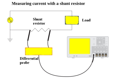
The voltage measurement can be taken across the portion of the circuit that you wish to sample, or it can be taken across a resistance that is put in series with it provided the circuit does not branch out between these loads. However, it must be realized that placing a resistance in series with a circuit element will divide the voltage and reduce the current. If the portion that is to be examined by the oscilloscope has a non-zero capacitive or inductive component, and if the power source is ac, there will be phase shift between voltage and current. But this does not prevent viewing the waveform.
In accessing the waveform across a pre-existing or inserted series resistance, great care must be taken that the return lead is not connected at a point where there is a voltage that is referenced to or floats above the premises branch-circuit ground, for reasons explained earlier.
All of the problems in displaying current using a voltage probe go away when using a current probe. Alternatively, the ground-fault hazard is avoided when using a hand-held, battery-powered oscilloscope with inputs that are isolated from one another and from ground. Some users prefer the bench-mounted oscilloscope because it has a more easily interpreted and detailed display, enhanced features and the possibility of greater bandwidth, deeper memory and potentially faster sampling rate.
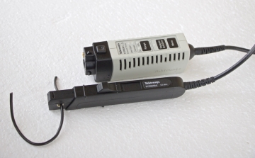
It is possible to connect bench-type oscilloscope probe leads to a floating, ground-referenced location as long as a specialized accessory known as a pair of differential probes is used. The two probe tips are touched to wires or terminals that are at different potentials, without regard to any ground relation. The difference is measured and displayed on the oscilloscope screen.
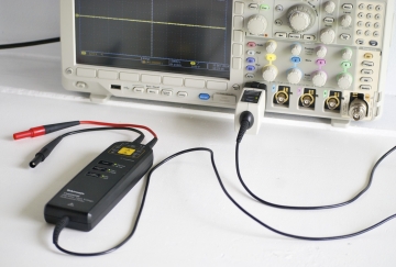
The object of the exercise, besides avoiding a ground fault hazard, is to maximize the common-mode rejection ratio. To this end, the two signal paths must be electrically identical insofar as possible, so the leads are best kept quite short. With advances in miniaturization, it has become possible to locate the differential amplifier in the probe head so the remainder of the signal path may be conventionally cabled.
Differential probes would be widely used were it not for the price. Some models are close to $30,000. For servicing a variable-frequency drive (VFD) or developing the product, a differential probe set is ideal. But many users are content to use a hand-held, battery-powered oscilloscope. This, in conjunction with the electrician’s clamp-on ammeter, will answer most questions concerning VFD operation in the field and in the laboratory during product development.

You left out the A-B mode of the vertical channels.
I haven’t been around any digital scopes but my old analog will subtract the voltage on channel B from the voltage on Channel A. = a differential probe.
To sum up we can use a shunt resistor or a current probe. Secondly you mentioned that current probes cost around 1000$ but there are cheap Chinese probes available on amazon now. Infact you can get branded probes like fluke 80i [ http://en-us.fluke.com/products/all-accessories/fluke-80i-110s.html ] or intellisense i2 [ https://www.taraztechnologies.com/product/intellisens-smart-pc-usb-probes/intellisens-i2-current-probe/ ] for around 400$ now.
GR8T read. Color me impressed
Interesting. I know it’s an old article but an idea about what the shunt resistance value should be (I guess 1 Ω would be quite practical).