• Skip to primary navigation
  • Skip to main content
  • Skip to primary sidebar
  • Skip to footer
  • Advertise
  • Subscribe

Test & Measurement Tips

Oscilloscopes, electronics engineering industry news, how-to EE articles and electronics resources

  • Oscilloscopes
    • Analog Oscilloscope
    • Digital Oscilloscope
    • Handheld Oscilloscope
    • Mixed-signal Oscilloscope
    • PC-based Oscilloscopes – PCO
  • Design
  • Calibration
  • Meters & Testers
  • Test Equipment
  • Learn
    • eBooks/Tech Tips
    • FAQs
    • EE Training Days
    • Learning Center
    • Tech Toolboxes
    • Webinars & Digital Events
  • Video
    • EE Videos
    • Teardown Videos
  • Resources
    • Design Guide Library
    • Digital Issues
    • Engineering Diversity & Inclusion
    • Leap Awards
    • White Papers
  • Subscribe
You are here: Home / Oscilloscopes / Mixed-signal Oscilloscope / Pico Technology’s mixed–signal oscilloscopes

Pico Technology’s mixed–signal oscilloscopes

December 6, 2012 By Test and Measurement Editor Leave a Comment

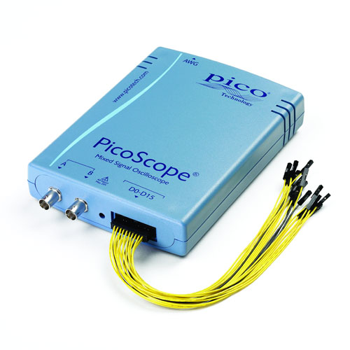
The new range of mixed–signal oscilloscopes (MSOs) from Pico Technology combines the deep memory and high performance of the PicoScope 3000 Series with a powerful 16–channel logic analyzer. With a built–in function generator and arbitrary waveform generator also included, these oscilloscopes offer a complete test bench in one compact, USB–powered device.

The new MSOs have 2 analog channels with bandwidths from 60 MHz to 200 MHz, a maximum single–channel sampling rate of 500 MS/s, and 100 MHz digital inputs.

Serial data in I²C, UART/RS232, SPI, CAN bus, LIN and FlexRay formats can be decoded and displayed in binary, decimal or hexadecimal formats. The 16 logic inputs are organized in two banks, each of which has its own adjustable logic threshold to allow testing of mixed-logic designs.

PicoScope

The PicoScope software supplied with the MSOs includes as standard all the oscilloscope and spectrum analyzer functions you would expect, as well as mask limit testing, segmented memory, advanced triggers and the serial decoding mentioned above: features that often cost extra on other manufacturers’ scopes. Other built–in features include persistence displays with fast update rates, math channels, automatic measurements with statistics, and programmable alarms. Updates to the software are free of charge.

The advanced trigger types include pulse width, interval, window, window pulse width, level dropout, window dropout, runt pulse, variable hysteresis, and logic. All triggering is digital, ensuring lower jitter, greater accuracy and higher voltage resolution than the analog triggering found on many competing scopes.

A free Software Development Kit (SDK) allows you to control the new scopes from your own programs. It includes example code in C, C++, Excel and LabVIEW, and can be used with any language that supports C calling conventions. The PicoScope software and SDK are compatible with Microsoft Windows XP, Windows Vista, Windows 7 and Windows 8.

Pico Technology
www.picotech.com
Filed Under: Mixed-signal Oscilloscope Tagged With: Pico Technology

Reader Interactions

Leave a Reply Cancel reply

You must be logged in to post a comment.

Primary Sidebar

Featured Contributions

Why engineers need IC ESD and TLP data

Verify, test, and troubleshoot 5G Wi-Fi FWA gateways

How to build and manage a top-notch test team

How to use remote sensing for DC programmable power supplies

The factors of accurate measurements

More Featured Contributions

EE TECH TOOLBOX

“ee
Tech Toolbox: 5G Technology
This Tech Toolbox covers the basics of 5G technology plus a story about how engineers designed and built a prototype DSL router mostly from old cellphone parts. Download this first 5G/wired/wireless communications Tech Toolbox to learn more!

EE TRAINING CENTER

EE Learning Center

EE ENGINEERING TRAINING DAYS

engineering
“test
EXPAND YOUR KNOWLEDGE AND STAY CONNECTED
Get the latest info on technologies, tools and strategies for EE professionals.
“bills

RSS Current EDABoard.com discussions

  • Why need use TOPmetal Stacking?
  • Monte-Carlo simulation error on ADE-XL
  • Snooping Around is All
  • Identification of a 6 pin smd chip (sto-23-6) marked E2
  • Dynacord enter protect

RSS Current Electro-Tech-Online.com Discussions

  • Does US electric code allow branching ?
  • Fun with AI and swordfish basic
  • using a RTC in SF basic
  • Faulty heat air gun (dc motor) - problem to locate fault due to Intermittent fault
  • Sump pit water alarm - Kicad 9
Search Millions of Parts from Thousands of Suppliers.

Search Now!
design fast globle

Footer

EE World Online Network

  • 5G Technology World
  • EE World Online
  • Engineers Garage
  • Analog IC Tips
  • Battery Power Tips
  • Connector Tips
  • DesignFast
  • EDA Board Forums
  • Electro Tech Online Forums
  • EV Engineering
  • Microcontroller Tips
  • Power Electronic Tips
  • Sensor Tips

Test & Measurement Tips

  • Subscribe to our newsletter
  • Advertise with us
  • Contact us
  • About us

Copyright © 2025 · WTWH Media LLC and its licensors. All rights reserved.
The material on this site may not be reproduced, distributed, transmitted, cached or otherwise used, except with the prior written permission of WTWH Media.

Privacy Policy