Advanced math functions in a digital storage oscilloscope involve, among other things, combining active and reference waveforms. First, we’ll see how reference waveforms are established in the instrument memory, and then return to advanced math.
Active waveforms correspond to electrical energy that is present at the channel inputs. Often, however, the user has reason to work with reference waveforms, which are inserted into the oscilloscope memory beforehand.
A primary use for reference waveforms is as standards against which other waveforms can be compared. In advanced math, a second signal is combined with an active signal to perform a math operation. To establish a reference waveform in the Tektronix MDO3000 Series oscilloscope, power up the instrument. Before beginning a new operation, it is a good idea to press Default Setup and Menu Off. Then, press R, which is located on the front panel between the screen and the Channel One button. This brings up the lower Reference menu, consisting of R1 through R4. Each of these menu selections displays a previous reference file with the date and time when it was created and placed in the oscilloscope memory. Any of these menu selections can be displayed by pressing the associated soft key.

With one of the reference waveforms and the vertical menu displayed, the current reference waveform can be moved along the Y- or X-axis by means of Multipurpose Knobs a and b or by using the keypad. Vertical settings are volts or fractions-per-division, and horizontal settings are seconds or fractions per division.
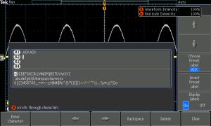
Press Edit Labels. Use the resulting menus to define labels and to display the current Reference waveform. After the reference file has been edited, press Reference Details to see the sample rate and record length. The default values are 250MS/sec and 10 K points respectively.
Press Save to File to store reference information in an external drive that has been inserted into the USB slot. You can display all four reference waveforms simultaneously merely by toggling the four soft keys on. One or more of them can be similarly toggled off.
You can position and scale a reference waveform independently from the others. Use Multipurpose Knob a with the reference waveform selected. When a reference waveform is selected, Wave Inspector is fully functional. Measure, Search, Test, Pan and Zoom all work and Markers can be set and cleared. If the screen doesn’t look right, press Autostart.
10 M Reference waveforms are volatile, which means they are not retained when the instrument is powered down. If they will be needed another day, save them to a flash drive.
Most digital storage oscilloscope makers have included Math capabilities in both bench-type and handheld, battery-operated instruments. The Math menu is typically further divided into Dual Waveform Math, FFT (Fast Fourier Transform) and Spectrum Math. These submenus come alive when the user presses a few soft keys and proceeds along the paths that are indicated.
Advanced Math may seem to have an imposing title, but in actuality, this area of the oscilloscope is quite user-friendly given the documentation provided by the major vendors. Navigating is self-evident. The gateway, of course, is the Math button. It is lighted in red, the dedicated Math color. From there, press the soft key directly below Advanced Math, one of the menu selections below the display. This brings up the vertical Edit Math Expression menu. The soft keys associated with the menu selections that have appeared allow us to create custom expressions. To see how this evolves, push the soft key adjacent to Edit Expression.

Some of the Advanced Math operations are:
• FFT
• Integrate
• Differentiate
• Log
• Exponential
• Square Root
• Sine
• Cosine
• Tangent
• Period
• Frequency
• Delay
• Rise
• Fall
• Positive Width
• Negative Width
• Burst Width
• Phase
• Positive Duty Cycle
• Negative duty Cycle
• Positive Overshoot
• Negative Overshoot
• Total Overshoot
• Peak-To-Peak Amplitude
• RMS
• Cycle RMS
• High
• Low
• Max
• Min
• Mean
• Cycle Mean
• Area
• Cycle Area
• Trend
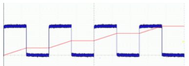
For example, we can use Edit Expression to take the integral of a square wave:
1. Push Clear on the lower menu.
2. Turn Multipurpose Knob a to select Intg (.
3. Press Enter Selection.
4. Turn Multipurpose Knob a to select AFG with Square Root displayed.
5. Press Enter Selection.
6. Turn Multipurpose Knob a to select ).
7. Press OK Accept.
Waveform Math provides some intriguing displays. Seeing how waveforms combine on an instantaneous point-by-point basis, we gain insight into how oscillating signals interact in electrical equipment and as electromagnetic waves travelling through space. Waveform Math is an important educational tool, but are there useful applications? Absolutely – Here are some examples:
An electrical signal can be conveyed as a differential pair, each on its own conductor plus a conductor that is common. In a cable such as unshielded twisted pairs (UTPs), the advantage is that noise and interference that is common to both leads is eliminated because the receiver responds only to the difference. This is called common mode rejection. Any interference or noise is applied equally to the two conductors, especially if they are twisted.
One of the things to realize about Waveform Math is that it is exceedingly sensitive. Accordingly, in the Add mode, it can be used to ascertain that the positive and negative swings of the differential pair are precisely equal and opposite.
Another application for Waveform Math is to calculate instantaneous power. When voltage is applied to a load that has some finite impedance, there are four metrics of interest: electromotive force in volts, current in amps, impedance in ohms, and power in watts. In electronic work these values often arise in small fractional units such as millivolts or even microvolts, but regardless, they are mathematically related and conform to Ohm’s law and the power law:
E = I x R
where
E = Volts (electromotive force)
I = Amps (intensity)
R = Ohms ( resistance or in an ac circuit, impedance)
and
E x I = P
where P = Power in Watts or Volt-Amps if ac
An oscilloscope in Measure mode can quantify volts and, using a current probe, can measure current.
It cannot, however, directly measure power. But using the Math mode, voltage and current can be multiplied, and the product is equal to the power that is transferred from the source to the load and then dissipated in the form of heat or applied as work or information.
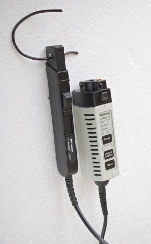
The current probe is a valuable accessory to have with an oscilloscope. It is similar to the electrician’s clamp-on ammeter, although somewhat smaller because it is generally intended to measure relatively small amounts of current.
A fundamental way to measure current is to cut one of the two circuit conductors and insert an ammeter in series with the power source and load. Because all the current passes through the ammeter, a large meter is required if the load is substantial. A current probe or clamp-on ammeter, in contrast, has jaws that can open and close around one of the conductors. The jaws have an inductive coil that senses the magnetic field and converts it to a voltage that is measured by the oscilloscope and displayed, calibrated in amps or fractions thereof. An experienced oscilloscope technician frequently has a clamp-on current probe and makes abundant use of it.

Leave a Reply
You must be logged in to post a comment.