Electricians know about Class 1, 2, and 3 wiring because these terms are spelled out in the National Electrical Code. Electronics engineers, however, tend to be in the dark about these terms. So here is a short primer on classes of wiring for the curious.
The NEC in Article 725 makes a sharp distinction between wiring for “ordinary” power and light circuits and specialized circuits where the power and/or voltage is limited. These circuits are designated Class 1, 2 and 3, not to be confused with the Class I, II and III hazardous locations – an entirely different matter.

Because these circuits are characterized by restricted use and more stringent electrical power limitations, requirements are somewhat relaxed regarding minimum wire sizes, ampacity correction and adjustment procedures, over-current protection, insulation requirements and wiring methods and materials. Many of these strategies are optional alternatives that can be chosen in the interest of reducing cost while maintaining protection from electrical shock and fire hazards.
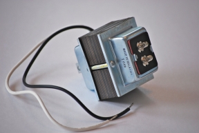
Class 1, 2 and 3 circuits are defined primarily in terms of the power supply to which they are connected. Power supplies are generally batteries, transformers or electronic power supplies. When working on an existing installation, it is a simple matter of identifying the power source and checking its marking. A Class 2 circuit associated with the electrical equipment that is part of a residential oil furnace, for example, usually receives power from a 24-V transformer whose primary connects to a 120-V premises branch circuit. The relatively high impedance of this small device ensures that its voltage and power output will be in the Class 2 range. Such a device will be marked as suitable as a Class 2 power source.
To ascertain the class of a specific installation, information comes from Part III of Article 725 in the NEC. It gives precise voltage and power limitations. Additionally, there are other factors that determine the classification. Class 1 is the most problematic, and as such it requires enhanced protection. The Code states that remote-control circuits for safety-control equipment is to be classified as Class 1 if failure of the equipment to operate introduces a direct fire or life hazard.
Room thermostats, water temperature regulating devices and similar controls used in conjunction with electrically-controlled household heating and air conditioning are not considered safety control equipment and hence are not Class 1. Similarly, fire alarm system wiring does not fall into this category because it does not introduce direct fire or life hazard. Instead, its function is to announce the presence of any hazardous occurrence.
Class 1 wiring is actually required to exceed standards for power and lighting wiring. It must sit in metal or non-metallic raceway or be metal-sheathed wiring as compared to jacketed cable such as type NM.
Class 3 wiring is functionally similar to Class 2 wiring, but with higher voltage and power limitations.
Major differences in the installation of Class 2 wiring are that conductor sizes 18 and 16 AWG are permitted and splices, such as with wire nuts, are permitted outside of conventional enclosures. This is the rationale underlying the use of open-backed wall boxes for low-voltage wiring. They are great cost and installation time savers and they do not have to contain sparks resulting from a fault because there is not enough electrical energy to create such sparking.

Would Using a 0 to 10v dimmer on multiple led drivers , still be considered class 2, assuming each driver is supplied by it’s own 2 wire conductor, but sum of all drivers is greater than 100m. I.e. dimmer rated at 8A.