• Skip to primary navigation
  • Skip to main content
  • Skip to primary sidebar
  • Skip to footer

Test & Measurement Tips

Oscilloscopes, electronics engineering industry news, how-to EE articles and electronics resources

  • Oscilloscopes
    • Analog Oscilloscope
    • Digital Oscilloscope
    • Handheld Oscilloscope
    • Mixed-signal Oscilloscope
    • PC-based Oscilloscopes – PCO
  • Design
  • Calibration
  • Meters & Testers
  • Test Equipment
  • Suppliers
  • Video
  • EE Learning Center
    • Design Guides
      • WiFi & the IOT Design Guide
      • Microcontrollers Design Guide
      • State of the Art Inductors Design Guide
      • Power Electronics & Programmable Power
  • FAQs
You are here: Home / New Articles / Basics of bandwidth in an oscilloscope

Basics of bandwidth in an oscilloscope

July 6, 2015 By David Herres 1 Comment

The bandwidth specification in an oscilloscope is applicable to digital as well as analog instruments. Early oscilloscopes, or more properly oscillographs, consisted of a magnetically-driven pen that would ink a trace on a turning paper cylinder, which provided the time base. Frequency response, of course, was severely limited by the mass and inertia of the pen and connected linkage, so maximum bandwidth was quite low.

In an effort to boost the bandwidth, oscilloscope builders soon moved away from the moving pen model. A vibrating mirror or the surface of a reflective liquid increased the frequency response dramatically, and cathode ray tube (CRT) technology made possible further advances.

bandwidth plot
The definition of bandwidth (B) for a scope. Here f0 is the center frequency, fH is the higher cut-off frequency, and fL is the lower cut-off frequency. The 0 dB level is the level of the peak of the scope response.

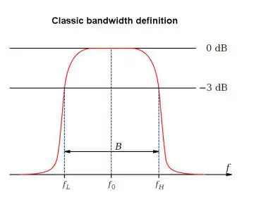
Today bandwidth in the context of the oscilloscope is taken to mean the maximum frequency that can transverse the front end without significant attenuation, defined as 70.7% (-3 dB) of the original signal. This attenuation comes from the combined effects of inductive reactance, a series phenomenon that rises at higher frequencies, and capacitive reactance, a parallel phenomenon that drops at higher frequencies. The two conspire to increase impedance as frequency rises, and the combination limits bandwidth.

This attenuation takes place throughout an old-style analog oscilloscope, and also in the analog front end of a digital instrument. Sample rate and memory depth are also important issues in a digital oscilloscope, but for now we’re talking about bandwidth exclusively.

Bandwidth becomes important when two frequencies combine, as in AM or FM broadcast, where a lower-frequency audio signal modulates a higher frequency carrier. Bandwidth is relevant also when there is any signal other than a pure sine wave or dc as shown by a straight horizontal line in the display. An example is the square wave with enormously fast rise and fall times, generating powerful harmonics. In this instance there is a significant bandwidth because of the large amount of power in the harmonics outside the fundamental frequency.

Even restricting the discussion to electronics, bandwidth has several distinct, though related, meanings. In digital processing, it is taken to refer to the range of frequencies of a single signal, expressed in hertz. When the context shifts to computing, the focus becomes speed of data transfer, expressed in bits per second (bit/sec). In physics, spectral bandwidth is the width of an atomic or molecular line in the spectrum, here again measured in hertz.

In choosing an oscilloscope, bandwidth is of great importance and it figures prominently in the price. A buyer should select a model having a bandwidth far in excess of the highest frequency to be measured. However, don’t go overboard. It all depends upon the anticipated usage. Other parameters such as sampling rate and memory depth, as well as quality of the probes will need to be considered.

Filed Under: New Articles

Reader Interactions

Leave a Reply Cancel reply

You must be logged in to post a comment.

Primary Sidebar

Current Digital Issue

A frequency you can count on There are few constants in life, but what few there are might include death, taxes, and a U.S. grid frequency that doesn’t vary by more than ±0.5 Hz. However, the certainty of the grid frequency is coming into question, thanks to the rising percentage of renewable energy sources that…

Digital Edition Back Issues

Oscilloscopes Finder

Search Millions of Parts from Thousands of Suppliers.

Search Now!
design fast globle

Subscribe to our Newsletter

Subscribe to test and measurement industry news, new oscilloscope product innovations and more.

Subscribe Today

EE TRAINING CENTER CLASSROOMS

EE Classrooms

RSS Current EDABoard.com discussions

  • Measuring a 1GHZ Signal
  • Need help in finding distributor having components
  • transient vs. pss simulation
  • DA14531 Bluetooth and Xamarin.
  • Digital Attenuator Power Dissipation

RSS Current Electro-Tech-Online.com Discussions

  • Is there a discord for this forum?
  • 2nd pcb design program?
  • How to power up two stereo audio amplifiers from a single source of power supply
  • Need help for diy ups project
  • cadence transient and pss simulation

Footer

EE World Online Network

  • DesignFast
  • EE World Online
  • EDABoard
  • Electro-Tech Online
  • Analog IC Tips
  • Microcontroller Tips
  • Power Electronic Tips
  • Sensor Tips
  • Connector Tips
  • Wire and Cable Tips
  • 5G Technology World

Test & Measurement Tips

  • Subscribe to our newsletter
  • Advertise with us
  • Contact us
  • About us
Follow us on TwitterAdd us on FacebookFollow us on YouTube Follow us on Instagram

Copyright © 2022 · WTWH Media LLC and its licensors. All rights reserved.
The material on this site may not be reproduced, distributed, transmitted, cached or otherwise used, except with the prior written permission of WTWH Media.

Privacy Policy