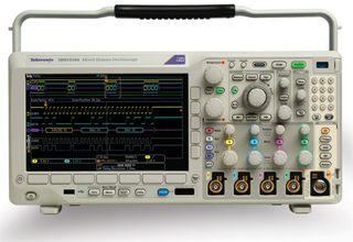
Today’s Digital Storage Oscilloscopes (DSOs) such as the Tektronix MDO3000 are capable of a wide range of complex operations, often involving substantial voltages from power sources having high available current. With proper care and maintenances, these instruments will last indefinitely. They seem never to wear out. Here are some suggestions for maximizing accuracy and longevity:
The bench-model oscilloscope is most at home in a dry, room-temperature lab, repair facility or classroom. For outdoor work or on the factory floor, the hand-held, battery-powered instrument with its ruggedized, dust- and moisture-resistant enclosure is more suitable. Moreover, the hand-held instrument is preferred for field work such as servicing a variable-frequency drive motor because its analog channel inputs are isolated from ground and from each other. Consequently, it can be connected to voltages referenced to but floating above ground potential without danger of high fault current.
Proper use of the bench-type oscilloscope, which is powered by ac mains, requires awareness of this issue for every hookup. Additionally, voltage limitations must be observed. The maximum voltage that can be safely measured is invariably printed on the front panel, together with Cat rating.
The DSO is made to be used. You don’t have to worry that it will explode if you press the wrong button. However, we have to note some restrictions. For one thing, if the instrument fails to perform as expected, unless you are an advanced electronic technician, resist the impulse to open the enclosure. Doing so will void the all-important traceable calibration as well as any product warranty that may be applicable. Also, high-bandwidth instruments are extremely sensitive to component alignment and cable routing, so even slight alterations can introduce instabilities that may be difficult to correct. New oscilloscopes can be expensive, but factory servicing is surprisingly affordable and it is generally possible to get a quote in advance.
All of that being said, there is quite a lot that can be done without opening the enclosure. Even when the oscilloscope’s operation appears normal and conforming to specifications, some manufacturer-recommended procedures should take place. The first and most basic is probe compensation. Vendors normally supply one probe for each channel. Probe compensation is necessary because small manufacturing differences make it probable that impedances at probe outputs will not exactly match impedances at channel inputs. Each probe must be individually compensated. For performing this simple operation, oscilloscopes have exposed terminals on the outside of their enclosures, which are energized by a low-voltage, high-frequency square wave. To perform probe compensation connect the probe tip and ground return lead to the two terminals as marked. With the oscilloscope turned on and the desired channel activated, connect the probe.
The square wave is displayed. If the probe is correctly compensated, the square wave will be well-formed with square corners, rise and fall times comprised of vertical lines and high and low voltages represented by horizontal lines. (It may be necessary to press Autoset.)

A Tektronix MDO3000 oscilloscope is capable of performing automatic compensation for TPP0250, TPP0500B and TPP1000 (the most common) passive voltage probes. To perform this compensation, connect the probe to the desired channel. Pressing the On button, a horizontal menu across the bottom in the second menu selection notes the type of probe that has been detected. Pressing More, a vertical menu appears on the right with the probe type and attenuation displayed, together with the compensation status. If you press the third menu selection, Compensate Probe, followed by OK Compensate, the process is completed within a couple seconds and the probe compensation status is updated.
It is possible to compensate a probe for more than one channel and also to compensate more than one probe to a single channel. Each compensation generates values for a specific probe/channel combination. Each channel can store compensation values for 10 individual probes. If you attempt to compensate an 11th probe on a channel, the oscilloscope will delete the values for the least-recently-used probe and add the values for the new probe. A factory calibration will delete stored compensation values.
With automatic compensation, you could conceivably compensate all probes to all channels, but the simpler procedure is to match each probe to a channel and use the colored snap-on rings that the manufacturer supplies to identify the probes.
A procedure that is similar to probe compensation is signal-path compensation. This operation should be performed if the oscilloscope is subject to temperature variations greater than 10°C (18°F), and also once per week if you require accurate readings of signals when vertical settings of 5 mV/div or less are used.
To compensate the signal path, warm up the oscilloscope for at least 20 minutes. Remove all input signals (probes and cables from all inputs). Any signal with an ac component will invalidate signal path compensation. Press Default Setup and Menu Off.
To begin, press the Utility button, located below the screen. In the horizontal Utility menu below the display, press Utility Page. In the vertical Utility Page menu at the left of the display, use Multipurpose Knob a to select Calibration. In the horizontal menu that appears across the bottom of the display, press the soft key associated with Signal Path. Read the explanatory material that appears onscreen. It is noted that Signal Path Compensation may take up to 10 minutes to run. The date of the last signal path compensation and number of operating hours since it was performed are noted.
To initiate Signal Path Compensation, in the vertical menu at the right of the display press the soft key associated with OK Compensate Signal Path. A turning wheel in the upper left corner of the display denotes that Signal Path Compensation is in progress. When Signal Path Compensation has been successfully completed, a message to that effect appears onscreen. You can press Default Setup and Menu Off, and the oscilloscope is ready to be used.
Another type of oscilloscope maintenance is upgrading the firmware. The manufacturer may have released a new firmware version for your oscilloscope. Or your instrument may be operating erratically or failing to go beyond the opening page. If so, installing new firmware or re-installing existing firmware may be the answer.
To perform this operation, go to the manufacturer’s website and navigate to software/downloads. Download the latest firmware for your oscilloscope onto your PC. Unzip the files and copy them to the root folder of a USB flash drive or USB hard drive. Power off the oscilloscope and insert the USB flash drive or USB hard drive into the USB port on the front panel of your oscilloscope. Then, power on the oscilloscope. It will automaticallly recognize and install the new firmware.
If the oscilloscope does not install the software, rerun the procedure. If the problem persists, go back to the manufacturer’s website and download the firmware on a different model USB flash drive or USB hard drive and follow the above procedure to install it in the oscilloscope.
In any event, do not power off the oscilloscope or remove the storage device until the installation is complete. If the installation still fails, contact the manufacturer’s tech help.
If successful, power off the oscilloscope and remove the USB flash drive or USB hard drive. Then, to verify the installation, restart the oscilloscope and press the Utility button. Go to the Utility page and select Config. In the menu that appears across the bottom, select About. Confirm that the version number matches that of your new firmware.
You can run a self-test on your oscilloscope. In Utility Page, use Multipurpose Knob a to highlight Self Test. Then, press Self Test in the horizontal menu at the bottom. Press OK Run Self Test.
A final note: The oscilloscope should not be left on for long periods of time when not in use. That would run up the hours unnecessarily. By way of perspective, a 40-hour work week for 50 weeks is equivalent to 2,000 hours per year. If the oscilloscope is On 10% of that time, it will amass 200 operating hours annually.


Want maintenance in Electronics lab.
Can you explain please why the oscilloscope should not be left on for long periods?
Also I leave my computer running 24/7, is that bad too?