Where the National Electrical Code (NEC) has been enacted into a jurisdiction’s body of law, it mandates every aspect of electrical installations from the point of view of safety. A lot of attention is focused on grounding and bonding. These related concepts are covered in detail in NEC Article 250.

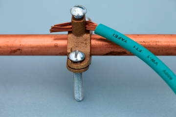
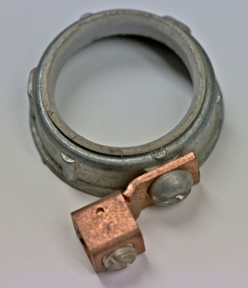
Grounding and bonding as electrical installation protocols overlap to a certain extent, but they are not identical. In bonding, the emphasis is on creating low-impedance electrical connections between two or more conductive (metallic) bodies that are not normally current-carrying. These bonded objects are usually but not always grounded. Often metallic bodies are bonded back to the enclosure of a load center, and ultimately to the neutral bar at the electrical service, which is in turn grounded.
The purpose of bonding is as follows:
• It ensures that normally non current-carrying conductive objects that are bonded are at the same electrical potential. If metal bodies that are not bonded are at significantly different voltage potentials, and if they are simultaneously contacted, there will be a shock hazard. If arcing occurs near combustible material, there will be a fire hazard.

• When bonded to the neutral bar at a breaker box, it facilitates the operation of the branch-circuit over-current device. If a conductive body that is not so bonded becomes energized due to a chafing wire or other electrical fault, the over-current device will not open the circuit because there is no flow of fault current through it. If the metal body is contacted by an individual who is grounded (as is usually the case), there will be a severe shock hazard.
• By bonding normally non current-carrying objects that are part of the electrical installation (such as metal conduit and enclosures) to the grounding system, it ensures that they cannot become energized.
Grounding is accomplished by connecting neutral conductors to the electrical grounding system, which is connected to the earth by means of one or more grounding electrodes, typically ground rods, plates or rings, buried metal water pipe, well casings or structural building steel in contact with the earth.
The purpose of grounding is to:
• Drain transient voltages (such as caused by lightning or fallen power lines) out of the system.
• Ensure, in conjunction with bonding, that normally non current-carrying conductive objects remain at ground potential.
• Control build-up of static charges that can damage sensitive electronic equipment.
It could be said that bonding is more critical than grounding, although that would be misleading because both are essential for a safe electrical system. Some manufacturers suggest that certain types of electrical equipment such as parking lot light fixtures on metal poles should be connected to local ground rods. This is unnecessary and erroneous where these grounding electrodes would not have low-impedance connections back to the grounding means at the electrical service.
It is OK to install properly connected ground rods at any location in the electrical system provided that they are properly bonded, but otherwise these are known as “floating grounds” and they should not be used.

Very helpful information!
I have read a lot of information electrical bonding.
All information I have read , dances around the issue
of bonding.
However will not answer the question in and of it’s self.
What is >>> bonding <<>> bond <<<.
Why is it a bond??
And why is it a bond??