Any conductive body has a certain finite inductance. This inductance is an intrinsic property of a conductive body and it is always the same, regardless of whether that conductor or device is energized in an electrical circuit or sitting on a shelf in a warehouse.
The inductance of a straight wire segment can be greatly increased by winding it in the form of a helical coil, whereupon the magnetic fields established around adjacent turns combine to create a single stronger magnetic field. The inductance of a coil varies with the square of the number of turns.
Inductance of a coil is also greatly increased if the coil is constructed around a core that is composed of a material having high permeability for magnetic flux. (Flux is the product of the average magnetic field times the perpendicular area that it intersects. Flux in a magnetic circuit is analogous to current in an electrical circuit.) This is the situation in utility-owned power transformers and other coils intended to operate at 50 or 60 Hz. Inductive effects are more pronounced at higher frequencies, so for an RF inductor an air core will usually suffice.
One of the defining qualities of a coil is that when the applied voltage is removed, interrupting the current, the magnetic field collapses and the electrical energy, previously used to create the magnetic field, is abruptly returned to the circuit. This is simply a manifestation of the fact that a magnetic field and a conductor moving relative to one another induce a flow of current in the conductor.
The rate of current change in an inductor is proportional to the voltage applied across it as defined by the well-known equation:
V = L dI/dt
Where L is inductance in henrys, V is voltage, I is current and t is time. Like a capacitor and unlike a resistor, the impedance of an inductor is frequency dependent. Impedance is the vector sum of resistance (when and if there is a resistor or equivalent in the circuit) and inductive or capacitive reactance. In a capacitor, higher frequency equates to lower capacitive reactance. In an inductor, higher frequency equates to higher inductive reactance. A coil offers no opposition to the flow of direct current except for:
• A small amount of resistance due to the ampacity of the wire
• Momentary inductive reactance when the coil is first energized, due to the work required to establish the magnetic field. (During rise time the dc is essentially ac.)
The equation for capacitive reactance is:
XC = 1/2πfC
Where XC = capacitive reactance in ohms; f = frequency in hertz; C = capacitance
The equation for inductive reactance is:
XL = 2πfL
Where XL = inductive reactance in ohms; f = frequency in hertz; L = inductance
These equations have a striking symmetry. One is the mirror image of the other, the difference being in the role played by frequency. In capacitive reactance, f is in the denominator while in inductive reactance it is in the numerator. Capacitive and inductive reactance, as well as generic impedance, are expressed in ohms as in dc resistance, and they fully conform to Ohm’s Law, the understanding being that these properties vary with frequency.
High-end multimeters often include a capacitance mode. To make this measurement, just probe the leads of the device under investigation. In the interest of safety and accuracy, a high-capacitance device such as an electrolytic capacitor may need to be discharged, using a reasonable resistance for an appropriate length of time. Shunting it with a screwdriver is not a good practice because the electrolyte can be punctured because of the heavy current involved, not to mention arc flash in big units. After discharging, verify by checking the voltage.
Capacitors measured by means of a multimeter in capacitance mode may be expected to read low by as much as 10%. This accuracy is sufficient for many applications such as the starting circuit for an electric motor or for power supply filtration. Greater accuracy is available by performing a dynamic test. One precision measurement strategy is to create a circuit that converts capacitance to frequency, which can then be determined using a counter.
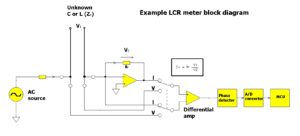
To measure the inductance of a device, intrinsic inductance of a circuit or more widespread distributed inductance, an LCR meter is the instrument of choice. It subjects the device under test (suitably discharged and isolated from any ambient circuitry that could energize it or create irrelevant parallel impedance) to an ac voltage of known frequency, typically one volt RMS at one kilohertz. The meter simultaneously measures the voltage across and current through the device. From the ratio of these amounts it algebraically calculates the impedance.
Subsequently, advanced meters measure the phase angle between the applied voltage and resulting current. They use this information to display the equivalent capacitance, inductance, and resistance of the device in question. The meter operates under the assumption that the capacitance and inductance it detects exist in either a parallel or series configuration.
Capacitors have a certain amount of unintended inductance and resistance as a result of their leads and plates. Similarly, inductors have some resistance because of their leads, and they have a certain amount of capacitance because their terminals equate to plates. Likewise, resistors, as well as semiconductors at high frequencies, acquire capacitive and inductive qualities.
Generally, the meter assumes the implied devices are in series when it makes LR measurements. Likewise, it assumes they are in parallel when CR measurements are made, due to the series geometry of the coil and the parallel geometry of the capacitor.
Both handheld and benchtop LCR meters in the more advanced models permit the user to select the frequency of the ac voltage to be applied. The rationale is that the inductor or capacitor being tested will react in a more characteristic fashion within a discrete frequency band.
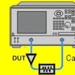
Benchtop LCR meters also usually incorporate a four-wire (Kelvin) option, which greatly enhances stability and accuracy in low-impedance measurements, where probe tip contact is likely to compromise the reading.
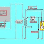
Inductance, capacitance, or resistance can all be measured via a bridge circuit. For this measurement, the variable calibrated elements are zeroed out at the detector, as opposed to measuring phase angle as in the conventional LCR meter.
When an LCR meter is not available, there are various methods for measuring inductance using an oscilloscope. One method, measuring inductance on a voltage-current slope, involves connecting the inductor to a pulsed voltage source with a duty cycle less than 50%. Using an oscilloscope’s current probe, read the peak current in amps and the time between pulses in microseconds. Multiply these amounts and divide the product by the peak current. This is the amount of inductance of the device being tested.
Another method for measuring inductance using an oscilloscope involves connecting a resistor of known value in series with the inductor under test and applying a signal. The frequency is adjusted so equal voltages appear across both devices.
 A third method for finding the inductance of a device consists of placing the inductor in parallel with a known capacitance. The resulting tank circuit is then placed in series with a resistor and the resonant frequency is found using an oscilloscope. From this, the inductance can be calculated.
These methods, while viable, entail some circuit work and extensive calculations, while the LCR meter provides a direct reading with sufficient accuracy for most applications.


Dear Sir !,
The important questions / a Induction Cooking !
1.How many volts is usually induction coil supply voltage? (600, 1000, 1200V?)
-True RMS multimetes?
– Oscilloscopes/pulse?
2. Is the frequency band 25-50 kHz?
3. What is the magnitude of the current, A (2000W coil)?
regards,
Kalervo Mattila
61800 Kauhajoki
Finland
e-mail. kalervo.mattila@anvianet.fi
Inductance reading is easy to measure if you use the right equipment or measurement tools. The multimeters and how to use them in order to measure the Inductance is not a job for an novice.
Is it necessary to take off the inductor from the circuit before mesuring it ?
Thank you for the informative article.
I figured out previously that C value is easy to equate with a 20 MHz scope’s series feedback (outin) probes.
The same never worked with various home-wound air coils and toroid chokes.
Now enlightened!! 🙂
What should be the frequency of LCR meter set to measure inductance of Alternator winding? At different frequency of measurement value of inductance values observed different.