The trapezoid-shaped 25-pin array inside the rectangular connector was a familiar sight a few years back, in an age when computers were connected primarily by means of the RS-232 bus. This old protocol seems rather clunky today alongside sleek new USB schemes with their many user benefits. However, RS-232 is far from obsolete. It is still widely used in programmable logic controllers (PLCs), networking equipment, and scientific instrumentation. This despite some downsides: low transmission speed, large voltage swings, and bulky connectors.
Unlike SPI, RS-232 was not a mere de facto standard. It was thoroughly codified by the Electronic Industries Association in RS-232-C (1969) with regard to electrical signal qualities including voltage levels, signaling and slew rate, timing, voltage-withstand level, and short-circuit and load capacitance metrics. The standard furthermore defined interface and connector construction and pin outs. Circuit functions were described in the manner of similar standards.
RS-232 was introduced in 1962 as an EIA Recommended Standard. At first it was envisioned to apply to teletype machinery with associated modems. Early terminals were built so as to be compatible with teletypewriting equipment. Accordingly, RS-232 remained relevant. However, a degree of confusion ensued because of proliferating peripheral devices that varied somewhat in electrical requirements, notably their use of reduced voltage levels.
The original RS-232 was less ambitious than more recent electronic bus protocols. One problem with the earlier design was that use of large voltage swings and the need for both positive and negative supplies resulted in excessive power consumption. Because of the voltage swing, maximum speed was limited. Also, noise immunity and transmission distance were compromised because of single-ended signaling referenced to a common signal ground.
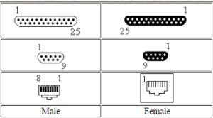
Multiple drops to three and more devices required improvisation, placing upper limits on speed and hampering compatibility. In an important respect, RS-232 resembled Ethernet in that to link identical computers or other devices, crossover cables were needed to matchup transmit and receive pins. This involved a larger media inventory, not to mention the possibility of error. Unlike USB, significant amounts of power could not be conveyed from host to peripherals. Moreover, with 25 pins at each end, cabling and terminations cost more, compromising an important rationale for the move from parallel to serial communication.
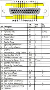
RS-232 is a single-ended as opposed to differential bus. Independent channels make possible full-duplex simultaneous communication between a central processing unit and its peripherals. Pin 2 transmits data and pin 3 receives data. Pin 4, request-to-send, is a signal sent from the transmitter; and pin 5, clear-to-send, is a signal sent from the receiver. Normally, these pins are on throughout the communication session. Pins 15, 17 and 24 are used to convey a clock signal, which is used only for synchronous communication.
Throughout any discussion of the RS-232 bus, the distinction must be kept in mind between Data Terminal Equipment (DTE) and Data Communication Equipment (DCE). Normally, a personal computer is DTE and the modem is DCE, regardless of which is transmitting at the moment.
The identity of any two units that are in communication can be ascertained by measuring the voltage on certain pins. Measure the voltage first between pins 2 and 7, and then between 3 and 7. Be certain in all cases that the black multimeter lead is connected to pin 7, which is signal ground. If the voltage on pin 2 is more negative than -3 V, you are looking at a DTE. If the voltage on pin 3 is more negative than -3 V, you are looking at a DCE.
This procedure presupposes, of course, that the system is wired correctly and that the pin outs correspond to the RS-232 standard.
It is easy to see why USB has replaced RS-232 as the predominant bus technology for data transfer between computers and peripherals as well as numerous similar applications in reasonably forgiving environments. But RS-232 remains the dominant data and clock bus on the harsh factory floor and in industrial locations world-wide, where the bulky, rugged connectors are actually a plus.
In addition to scientific instrumentation, production facilities make use of RS-232 in PLCs, which are generally connected to and controlled by ruggedized laptop computers through Ethernet, RS-232, RS-485 or RS-422, all related technologies. While a variety of programming software is possible, among the most-used variant is ladder logic. RS-232 in conjunction with ladder logic works well in harsh factory-floor environments where robust enclosures and tough cabling and connectors are needed to meet the challenges presented by temperature swings, dust, vibration and the possibility of moisture.
RS-232 may consist of either synchronous or asynchronous transmissions. The many lines include those for data as well as for control information. Each of these circuits operates in one direction only, either from the central unit to a peripheral or in the reverse direction. Because these circuits are separate, they can work simultaneously, so the system is capable of full duplex information transfer. RS-232 doesn’t use character framing and encoding.
The voltage levels by definition in RS-232 for logic high and logic low are +3 to +15 and -3 to -15 respectively. So -3 to +3 is a restricted zone, meaning it is not a valid R-232 level with reference to the common ground pin. In data transmission, logic one, the negative voltage, is known as “mark.” Logic zero, positive, is called “space” in the RS-232 bus.
Opposite polarity is used for the control signals, which is to say that positive voltage is the active state while negative voltage is the inactive state. This is in contrast to SPI, where zero volts on the SS line selects a particular slave and presence of voltage deselects it.
RS-232 requires a stable zero volts on the ground pins at both ends of the cable. If there is a significant difference, a ground loop will exist and there will be circulating electrical current. For this reason, RS-232 cable is restricted to relatively short lengths. RS-422, RS-485 and USB employ differential signaling with common mode rejection, and this permits longer cable lengths.
Rather than a maximum cable length, RS-232 mandates the amount of capacitance to be tolerated by any drive circuit. General use cables that comply with the standard will usually have too much capacitance if their length exceeds 50 ft. Special low-capacitance cables maintain full functionality in lengths up to 1,000 ft. Cable quality must be closely monitored to prevent harmful crosstalk between data and control lines.
RS-232 communication can be accomplished through cabling that has far fewer conductors than are suggested by the multi-pin connectors used at the ends. As few as two wires, data and ground, are used for one-way transmission in equipment as diverse as postal meters and GPS receivers that transmit position only. Five conductors are needed for two-way data plus hardware control.
To troubleshoot an RS-232 system, a digital probe perhaps in conjunction with a pulser will show the data and control high and low states. Y cables permit the technician to monitor traffic in both directions. A serial line analyzer is capable of checking RS-232 voltage levels, connectors and clock signals. This instrument will collect, store, and display the data and control signals.
Some of these instruments only display the signals as waveforms. Others can decode characters in ASCII and interpret protocols commonly used in an RS-232 bus including SDLC, HDLC, DDCMP, and X.25. Various types of serial line analyzers take the form of bench-type units or as software with cable accessories for logic analyzers and oscilloscopes. There are also available programs for laptop and desktop computers.
Because RS-232 is potentially a full-duplex bus, it needs separate send and receive lines. The Tektronix Demo 1 Board contains a terminal, labeled on the board, from which an RS-232 transmit signal can be obtained. The probe hook tip is connected to this terminal and the ground return lead is clipped onto one of the board’s ground terminals.
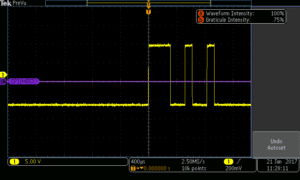
After the Demo 1 Board has been powered up using the specialized Y USB cable, with the probe connected to an analog channel input, the trace is shown on the oscilloscope screen. To get a clear display, first press Autoset, then turn the Scale knob associated with the analog channel that is being used.
We have seen some aspects of RS-232 that are less developed and user friendly. It is sometimes considered primitive in comparison to other bus types. But its rugged hardware and trouble-free software attributes ensure that it will for the foreseeable future remain the best choice in industrial and scientific applications. As a matter of fact, serial ports with RS-232 bus technology have been used extensively and to good effect in the International Space Station, where reliability is a primary consideration.

Leave a Reply
You must be logged in to post a comment.