• Skip to primary navigation
  • Skip to main content
  • Skip to primary sidebar
  • Skip to footer

Test & Measurement Tips

Oscilloscopes, electronics engineering industry news, how-to EE articles and electronics resources

  • Oscilloscopes
    • Analog Oscilloscope
    • Digital Oscilloscope
    • Handheld Oscilloscope
    • Mixed-signal Oscilloscope
    • PC-based Oscilloscopes – PCO
  • Design
  • Calibration
  • Meters & Testers
  • Test Equipment
  • Suppliers
  • Video
  • EE Learning Center
You are here: Home / FAQ / Basics of oscillators

Basics of oscillators

November 24, 2014 By David Herres Leave a Comment

A previous article discussed resonant circuits. Now we’ll go on to look at that fundamental workhorse of the modern electronic world, the oscillator. Without it, radio and TV transmission and reception as we know them would not be possible. There are countless other applications, from the microwave oven with its high-frequency force field, to the function generator embedded in the Tektronix MDO 3104 oscilloscope.

We have seen that a resonant circuit, because of equal inductive and capacitive reactances, can output electrical energy at discrete frequencies. Because of inevitable electrical resistance in the circuit, the voltage at the output will diminish, approaching zero. This is known as a damped wave, and it is common in electrical and nonelectrical oscillating energy in nature.

An oscillator implies a continuous sustained output. To maintain a continuous output, there must be an ongoing supply of new energy. The energy must come from an electrical circuit, a dc power supply, or some other kind of generator. The same situation exists for a clock mechanism where a spring or set of weights feeds stored energy into the system.

Many types of oscillators can be constructed from simple electrical components, powered by a nine-volt battery. The frequency can be regulated by a variable resistance and the output shown by a blinking LED or a loudspeaker emitting an audio tone, as appropriate to the frequency. The output can also be shown on an oscilloscope, the precise frequency shown by means of an internal frequency counter.

Oscillators are divided into two categories, the linear (harmonic) oscillator that outputs a sinusoidal waveform, and the non-linear (relaxation) oscillator.

The linear oscillator is further subdivided into the feedback type and the negative resistance oscillator.

linear phase shift oscillator via op amp
A simple phase-shift linear oscillator. The output is fed back to the op amp input through a phase-shift network consisting of resistors and capacitors which shifts the phase of the amplifier output by at least 180 degrees at the oscillation frequency to give positive feedback.

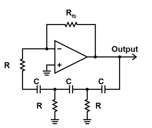
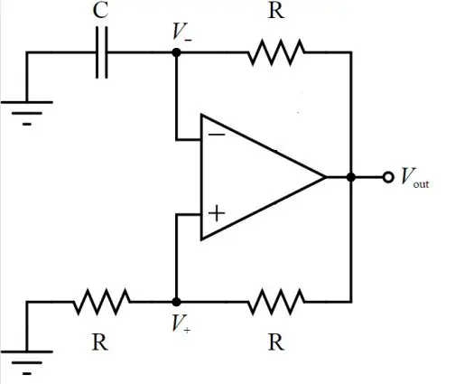
The linear oscillator can take the form of a simple transistor or op amp. What makes it work is a feedback loop. When power is turned on, the electronic noise floor initiates oscillations, which are amplified and returned to the input. The frequency quickly stabilizes to a precise value that depends upon the resonant circuit. Component values are chosen so  the amplitude is sustained and the waveform is not damped.

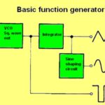
A relaxation oscillator is nonlinear. It outputs a non-sinusoidal signal. Some examples are the square wave and the triangle wave. The relaxation oscillator contains a switching device that is saturated for a good part of the cycle. Relaxation oscillators are widely used in low-frequency applications where the output is a blinking light, audio beeper or the like.

comparitor based relaxation oscillator
A relaxation oscillator that puts out squarewaves, based on a comparator. As comparator output moves away from zero, positive feedback makes the output saturate at either the positive/negative rail. A series RC circuit connects the output and inverting input so the inverting input approaches the output V with a time constant RC. When inverting input V exceeds non-inverting input V, the comparator output falls quickly. The difference between inputs gets more and more negative, the inverting input approaches the comparator output V, and the cycle repeats.

Crystal oscillators are appropriate where a precise output frequency is desired. A quartz crystal, which has piezoelectric properties, replaces the tuned circuit. It vibrates at a prescribed frequency, and the oscillations are maintained at a uniform level by means of a connected power supply and amplifier. Crystal oscillators are used to control the frequencies in radio transmission and to provide the clock signals in computers and quartz timepieces.

You may also like:

  • LIGO schematic
    Detecting gravitational waves

  • The difference between noise and jitter
  • OEO
    Understanding and measuring optoelectronic oscillators

  • Overview of electrical measuring instruments, Part 3
  • function generator
    The ups and downs of oscillators in test equipment

Filed Under: FAQ, Featured

Reader Interactions

Leave a Reply Cancel reply

Your email address will not be published. Required fields are marked *


This site uses Akismet to reduce spam. Learn how your comment data is processed.

Primary Sidebar

Test & Measurement Handbook


Oscilloscopes Finder

Subscribe to our Newsletter

Subscribe to test and measurement industry news, new oscilloscope product innovations and more.

Subscribe Today

DesignFast

Component Selection Made Simple.

Try it Today
design fast globle

EE TRAINING CENTER CLASSROOMS

“ee

“ee

“ee

“ee

RSS Current EDABoard.com discussions

  • RF detector can oscillate?
  • How to select a Frequency Multiplier (minicircuit)
  • Regarding Circular Polarization
  • How to increase bandwidth of printed yagi antenna?
  • SRF and Operating frequency for inductor

RSS Current Electro-Tech-Online.com Discussions

  • Dead Battery circuits.
  • This part is driving me nuts .....
  • Simple class A amplifier how it works
  • Difference between WSN and IoT network
  • Any advice on identifying the HV wires on an old flyback.

Follow us on Twitter

Tweets by TestAndMeasure

Footer

EE World Online Network

  • DesignFast
  • EE World Online
  • EDABoard
  • Electro-Tech Online
  • Analog IC Tips
  • Microcontroller Tips
  • Power Electronic Tips
  • Sensor Tips
  • Connector Tips
  • Wire and Cable Tips
  • 5G Technology World

Test & Measurement Tips

  • Subscribe to our newsletter
  • Advertise with us
  • Contact us
  • About us
Follow us on TwitterAdd us on FacebookFollow us on YouTube Follow us on Instagram

Copyright © 2021 · WTWH Media LLC and its licensors. All rights reserved.
The material on this site may not be reproduced, distributed, transmitted, cached or otherwise used, except with the prior written permission of WTWH Media.

Privacy Policy