Gustav Kirchhoff (1824-1887) was an accomplished Prussian physicist and instrument maker, and best known for his current and voltage circuit laws. Kirchhoff’s first circuit law, known as his current law, states that the algebraic sum of currents in a network of conductors meeting at a point is zero. Kirchhoff’s second circuit law, known as his voltage law, states that the sum of the voltages, taking into account their polarities, in a closed circuit is zero.
Kirchhoff’s current law is based on conservation of charge, measured in coulombs, which is current integrated over (multiplied by) time. SPICE and similar circuit simulation software make use of a matrix version of Kirchhoff’s current law along with Ohm’s law to perform nodal analysis of more complex circuits. So you would think that at this point, there is little that is controversial about Kirchhoff’s laws. That brings us to a series of YouTube videos that, surprisingly, explore the idea that Kirchhoff’s laws might not hold under certain circumstances.
The video that got the ball rolling on this topic wasn’t by somebody on the scientific fringe. It was by former M.I.T. Prof. Walter Lewin who claimed that it is a crime to teach that Kirchhoff’s voltage law is an absolute because it doesn’t always hold true in fact. He goes on to say the vast majority of physics textbooks are wrong on this point and that the many physics professors and electrical engineering professors who disagree with him are wrong and, finally, that if you disagree with him you simply don’t understand Faraday’s law.
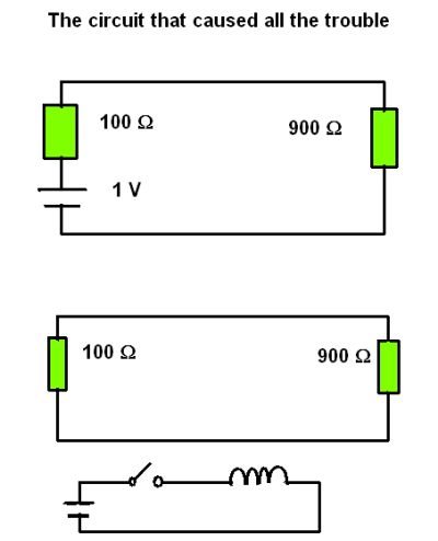 Lewin makes his point by describing a 1-V battery in series with two resistors having values of 100 and 900 Ω for a total resistance of 1,000 Ω. Thus there will be a conventional current through the circuit of 1 mA. A key point to note is where a volt meter is placed in this circuit to measure specific parameters. Putting the volt-meter across the 900-Ω resistor will give a reading of 900 mV; across the 100-Ω resistor will give a 100-mV reading. Of course, Kirchhoff’s voltage law says the voltage source should add up to the voltage drops across the resistances. So far so good.
Then Lewin removes the battery from the circuit so it is just comprised of a loop containing the two resistors. Near this circuit he introduces a coil in series with a switch and a battery. When the switch closes is causes a surge of current through the coil that creates a magnetic field. As time goes by that magnetic field increases. The increasing magnetic field induces a current in the closed loop containing the two original resistors. As the magnetic field rises, so too does the current in the two-resistor loop. Now assume that at a particular point in time the rising magnetic field induces a 1 mA current in the two-resistor loop. Thus there would be 1 mA through 900 Ω giving 900 mV and 1 mA through 100 Ω giving 100 mV, for a total of 1 V.
Thus we have the two voltage drops in a closed circuit. But there is no voltage source in this circuit, at least not one that is directly wired in. So the sum of the voltage drops plus the (in this case nonexistent) voltage sources don’t equal zero as Kirchhoff’s Law specifies. Hence the controversy.
Of course, in actuality the wires in the two-resistor closed-loop constitute the secondary of a transformer. The transformer primary is the battery/switch/coil circuit. At the moment in time where 1 mA is induced in the loop, we still see 100 and 900 mV induced across the two resistors. A point to note is that the resistor/transformer secondary loop can be viewed as a parallel circuit where the transformer secondary is in parallel with the two resistors. The rule about parallel circuits is that the voltage is the same everywhere. Thus there is one volt across the two resistors, one volt across the transformer secondary.
Now suppose we freeze time, a thought experiment that allows us to analyze the changing voltages in the circuit as if in a dc circuit. In that case the transformer secondary can be modeled as a 1-V battery. Then we would still see 900 and 100 mV drops across the two resistors. Adding the two voltage drops with the 1-V source sums to zero as Kirchhoff’s law specifies.
Again, so far so good. But in Prof. Lewin’s thought experiment he specifies that the wires between the two resistors are superconductors and thus have no resistance. Thus the wires constituting the secondary of the transformer have zero ohms of resistance. In other words, we have a voltage across something that has zero resistance. But according to Ohm’s law, there can’t be a voltage across something that has zero resistance. Hence the problem with Kirchhoff’s law.
Video bloggers such as RSD Academy’s Bob DuHamel and ElectroBoom’s Mehdi Sadaghdar say this is a misunderstanding of Ohm’s law. Here we’ll summarize the explanation as related in a video by Bob DuHamel. DuHamel begins by pointing out that Georg Ohm’s original experiment used a thermocouple as a voltage source. Ohm found that his famous equation wouldn’t work unless he allowed that the voltage source itself had a resistance. And this resistance had to be treated as if it was in series with the source. Today, when we write Ohm’s law for a circuit, we are generally lumping the source resistance in with the rest of the circuit resistance.
With regard to the circuit in the thought experiment, the implication is that the two lengths of wire serving as the secondary of a transformer must be modeled as a source plus a source resistance. If we assume that the wires are superconductors, then their source resistance is zero. But the source resistance is in series with the source, not across it. Consequently, if we assume the source resistance is zero, we simply have an ideal voltage source with zero internal resistance. Hence Ohm’s law still holds.
Lewin made the same argument for another simple circuit composed of a voltage source, a switch, and a series circuit composed of an inductor, capacitor, and a resistor. In this case, he assumes the inductor is comprised of superconducting wire and thus drops zero volts when the switch closes to complete the circuit. Thus he says Ohm’s law predicts zero volts across a superconducting inductor.
However, explains DuHamel, the inductor behaves like a voltage source when it stores energy and trying it impart it in a direction opposing that of the original current flow. Thus the inductor storing energy has a source resistance that is in series with the source voltage and, consequently, a voltage does indeed appear across the superconducting inductor.
Prof. Lewin suggests in his video that those who disagree with him don’t understand conservative and non-conservative fields. Conservative nature of an electric field means that the line integral of electric field along a closed path is zero. For a simple example, consider a circuit composed of two 1-V batteries in series with two one-ohm resistors. Starting at the negative terminal of the first battery, energy rises from zero to 1 V through the first battery, rises again from 1 V to 2 V through the positive terminal of the second battery, then drops by one volt as it passes through the first resistor, then finally drops from 1 V to zero volts as it passes through the second resistor. Thus in a conservative field (or loop), we gain potential and use it all doing work.
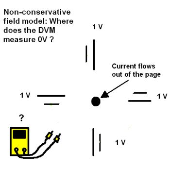 A non-conservative field is one where the integral along some path is not zero. Here, consider the coil in the first example circuit. When it is energized, it produces a changing magnetic field that in turn causes an electric field. And the electric field has a rotational component to it. The electric field can be represented by a series of 1-V batteries oriented in a circle around the coil wire. The key point is that one can’t determine where the zero-volt point resides in the circle of batteries. Thus there is no gain or loss of potential as we travel around the circle.
The interpretation of this model is that an electron in the field is seeing a 1-V rotational force. Now suppose there is a wire loop in the field carrying electrons. Now further suppose there is a break in the wire. A voltmeter placed across the gap in the wire will measure a voltage that can be used to do work. Because the loop is now a voltage source, it must have a series resistance. Thus the E field that is moving the current is still non-conservative but the potential developed across the gap is conservative. If a resistor is placed across the gap, work will be done as current flows through it. Thus we have a conservative circuit imbedded in a non-conservative field.
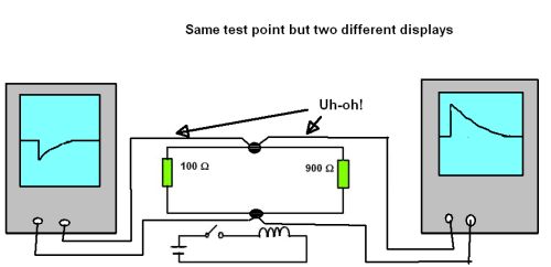 Finally, Prof. Lewin attached two different oscilloscope probes to the original two-resistor loop. Both probes were attached at the same point; that is, both positive probes at one side of the two-resistor connection, both scope ground connections at the other side of the two-resistor connection. But when the switch closed on the near-by coil, the two resulting voltage-spike scope traces differed from one another, though both connections were at the same point in the circuit.
As DuHamel and other video bloggers have explained, the ambiguity of the differing scope displays can be explained by the scope probes sitting in different parts of the magnetic field generated when the switch closes. Thus the scope probe sitting near the larger resistor displays a larger spike because the magnetic field generated by the closing switch also induces a current in the scope probes, not just in the circuit being measured. Similarly, the scope probe sitting near the smaller resistance are experiencing an induced current smaller and in the opposite direction of the other scope probe, because it is influenced by the field in the smaller resistor. Video bloggers that include Mehdi Sadaghdar have demonstrated the effect by using one scope probe and just repositioning it near one or the other resistors, then rerunning the demo.
So who knew Kirchhoff’s Law could cause arguments 187 years after it was discovered?



Leave a Reply
You must be logged in to post a comment.