Here’s a look at testing necessary for super-high throughputs involved in the emerging area of 6G.
Greg Jue, Keysight Technologies
6G research is in its early stages. The vision for what the International Telecommunication Union calls Network 2030 continues to take shape. While the industry is years away from starting the standards development process, subterahertz (sub-THz) territory is a focus of active research.
Data throughputs of 100 gigabits per second (Gbps) to one terabit per second (Tbps) are key objectives for 6G. This extreme data throughput could evolve into a key performance indicator (KPI) for 6G. However, the throughput jump poses significant challenges for both RF and baseband technologies.

There are three fundamental approaches to increasing data throughput. The first employs higher-order modulation schemes such as 64 QAM to boost the number of bits transmitted for each symbol. Given a fixed and finite spectrum bandwidth, increasing the modulation order from QPSK (transmitting two bits for each symbol) to 64 QAM (transmitting six bits for each symbol), would raise the data throughput by a factor of three, if channel conditions and radio performance allow. A 1-GHz QPSK symbol rate would result in a 2 Gbps theoretical raw calculated data throughput without forward error correction (FEC) coding rate redundancy. However, raising the modulation order to 64 QAM would bring a 6-Gbps data throughput, while using the same spectrum-occupied bandwidth.
The second approach uses more spectrum bandwidth and hikes data throughput by using a higher symbol rate. For example, the occupied channel bandwidth is approximately 1.22 GHz with a 1-GHz symbol rate , assuming a 0.22 root-raised cosine filter alpha (or excess bandwidth). (A root-raised-cosine filter is frequently used as the transmit and receive filter in digital communications to perform matched filtering and thereby help minimize intersymbol interference.) Increasing the symbol rate by a factor of ten to 10 GHz would raise the QPSK data throughput to 20 Gbps but would use a much wider swath of spectrum (about 12.2 GHz). Raising the modulation order to 64 QAM could increase the data throughput to 60 Gbps. But supporting higher-order modulation schemes at these extreme modulation bandwidths becomes much more challenging because of reduced Signal-to-Noise (SNR) ratio, greater linear amplitude and phase impairments, and other technical challenges.
A third approach transmits multiple and independent streams of data for higher data throughput using multiple antenna techniques such as multiple-input/multiple-output (MIMO). However, the actual increase in data throughput would depend on the channel conditions and system overhead.
A review of the first two approaches at H-band (220-330 GHz) from an RF physical layer perspective shows it’s possible to exceed 100 Gbps using 64 QAM modulation with an occupied bandwidth of 30 GHz.
IEEE 802.15.3d
The standardization process has yet to begin for 6G. However, IEEE 802.15.3d is an example of an existing standard for fixed point-to-point applications using the sub-THz frequency range between 252 and 325 GHz. In addition, IEEE 802.15.3d defines physical layer modes that enable data rates of up to 100 Gb/sec using bandwidths up to  69.12 GHz. Table 6-17j in the IEEE 802.15.3d specification shows eight different bandwidths supported for the sub-THz physical layer.
The bandwidths are multiples of the IEEE 802.11ad/ay channel bandwidths of 2.16 and 4.32 GHz, respectively. Row 1 represents the 802.11ad channel bandwidth of 2.16 GHz. Row 2 represents the 802.11ay two-bonded channel (CB2) bandwidth of 4.32 GHz. (Channel bonding in IEEE 802.11 means adjacent channels within a given frequency band are combined to boost throughput between wireless devices.) Row 3 represents the 802.11ay four-bonded channel (CB4) of 8.64 GHz. Rows 4-8 represent integer multiples of the 802.11ay CB2 and CB4 channel bandwidths up to 69.12 GHz.
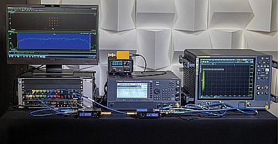
Our sub-THz testbed for H-Band, 220-330 GHz uses a 92 GSa/sec M8196A arbitrary waveform generator (AWG). This AWG generates wide bandwidth-modulated intermediate frequency (IF) signals and has an analog bandwidth of 32 GHz. A compact WR3.4 H-band upconverter converts the IF frequency from the AWG to the desired sub-THz frequency. This upconverter uses a 12x multiplication factor for the local oscillator (LO) frequency. An E8257D PSG vector signal generator with option UNY provides a low-phase-noise LO for the upconverter and downconverter. A PM5B power meter with WR3.4 waveguide taper measures the power.
On the receive side, the compact WR3.4 H-band downconverter converts the sub-THz frequency to an IF frequency. A UXR multichannel high-performance oscilloscope with a sample rate of 256 GSa/sec digitizes the IF signal. The configuration described here is for an over-the-air (OTA) transmission using diagonal transmit-and-receive horn antennas. Measurements also took place waveguide-to-waveguide using a WR3.4 waveguide bandpass filter, or a WR3.4 waveguide through-section for wider modulation bandwidth test cases.
This testbed is scalable across D and G sub-THz frequency bands by using different VDI converters and a M8195A 65 GSa/sec AWG. It is also flexible in terms of waveforms because it uses numerous software platforms to generate and analyze candidate waveforms. The testbed supports software written for test applications, as well as system design software and VSA software. Because the testbed AWG and oscilloscope are multichannel, the number of channels is scalable for MIMO research.
Measurement examples
Measurements took place for 4.32, 8.64, 12.96, and 17.28 GHz test cases with a WR3.4 bandpass filter and WR3.4 through-section to connect the compact upconverter and

downconverter. In addition, for the 25.92 GHz bandwidth test case, the symbol rate was set to six times the 802.11ay CB2 symbol rate (6 x 3.52 GHz = 21.12 GHz). The channel bandwidth is six times the 802.11ay CB2 channel bandwidth (6 x 4.32 GHz= 25.92 GHz). This bandwidth exceeds the WR3.4 bandpass filter’s bandwidth, so it was removed for this test.
The measured occupied bandwidth is 25.7 GHz, which corresponds to the 21.12 GHz symbol rate multiplied by the root raised-cosine (RRC) filter alpha (21.12 GHz x 1.22= 25.76 GHz). The symbol rate was 21.12 GHz, so the theoretical raw calculated data rate without forward error correction (FEC) coding rate redundancy comes to 21.12 Gsymbols/sec x 4 bits/symbol (16 QAM) = 84.48 Gb/sec for a single stream of data.
To push the data throughput rate beyond 100 Gb/sec, the 802.15.3d 21.12 GHz symbol rate was increased to 25 GHz. The modulation order was also hiked from 16 to 64 QAM to transmit 6 bits/symbol instead of 4 bits/symbol.
Measurements performed for the OTA test case are shown here. The OTA measurement results include baseband complex precorrections applied and an approximate six-inch edge-to-edge spacing between the VDI compact upconverter and downconverter.
The measured occupied bandwidth is 30 GHz, which corresponds to the 25 GHz symbol rate multiplied by the root raised-cosine (RRC) filter alpha (25 GHz x 1.22= 30.5 GHz). The symbol rate was 25 GHz, so the theoretical raw calculated data rate without forward error correction (FEC) coding rate redundancy comes to 25 Gsymbols/sec x 6 bits/symbol (64 QAM) = 150 Gb/sec for a single stream of data. Lowering the modulation order to 16 QAM would yield 100 Gb/sec.
A point to note is this extreme data throughput could evolve into a key performance indicator (KPI) for 6G. IEEE 802.15.3d is an example of an existing fixed point-to-point standard in the sub-THz frequency range between 252 GHz and 325 GHz.
Acknowledgment – Keysight Technologies acknowledges Virginia Diodes Inc. (VDI) for providing the VDI H-band WR3.4 220-330 GHz hardware described here.
References
A New Sub-Terahertz Testbed for 6G Research


Leave a Reply
You must be logged in to post a comment.