The common temperature probe contains a thermocouple consisting of two dissimilar metals welded together to form an electrical junction. A voltage that varies with temperature is generated. Slightly less accurate than resistance temperature detectors (RTDs), thermocouples cover a wide temperature range and respond quickly.
Combinations of different metals create different voltage responses. All dissimilar metals used to construct thermocouples display a change in voltage from the Seebeck effect, but several specific combinations are used to make commercial thermocouples. These senors can be divided into two types: base metal and noble metal thermocouples.
 Base metal thermocouples are the most common. Noble metal thermocouples use precious metals such as platinum and rhodium. Noble metal thermocouples are more expensive and are used for measuring higher temperatures.
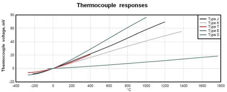
Each thermocouple type is designated by a single letter to indicate the two metals it contains. For example, a J-type thermocouple contains iron and constantan. The thermoelectric properties are standardized for each type so temperature measurements are repeatable. Thermocouple leads and connectors are also standardized with color plugs and jacks, indicating the type of thermocouple. Different colors for insulation and lead wires also indicate the thermocouple grade and extension grade.
The most common thermocouple is the Type K. Its continuous-duty temperature range is 0 to 1,100°C. The sensitivity is 41 μV/°C. The two metals are chromel and alumel. Chromel is a 90% nickel, 10% chromium alloy. Alumel is an alloy comprised of 95% nickel, two percent aluminum, two percent manganese and one percent silicon. A quality of thermocouples made with magnetic materials such as nickel is that the temperature sensitivity deviates at its Curie point, which happens for Type K thermocouples at 185°C.
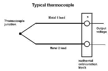
For accurate measurements, the return leads of the thermocouple’s different metals must be at the same known temperature. Also, any connection between two different metals creates a thermocouple junction. Thus connections from the thermocouple to the measuring instrumentation should be simple and symmetric to avoid unintentional thermocouple junctions.
Because both sides of the bimetal junction are ideally at the same temperature, there’s no voltage differential at that point. In reality, the voltage differential is the result of the temperature gradient along the wire between the junction and the reference point.
Thermocouple outputs are small, usually measured in microvolts. Thus the measurement instrumentation must be sensitive enough to work with these small signals. The measuring instrument also must be impedance-matched to prevent loading the circuit.
Another point to note about thermocouples is their output over temperature is nonlinear. Consequently, the International Temperature Scale of 1990 (ITS-90) standard defines equations that correlate thermoouple temperature and voltage output. This data is available on the National Institute of Standards and Technology (NIST) website (http://srdata.nist.gov/its90/main/).
Because the voltage created from the thermocouple is non-linear depending on the temperature of the cold junction at the measuring instrument, what’s called cold-junction compensation is necessary. A cold-junction block connects the thermocouple leads to the measurement instrument. This block holds both thermocouple leads at the same temperature and is often a connector made from a large metal mass. Air currents may affect the temperature, so it may be wise put the block in an enclosure.
An accurate measurement of the cold junction block acts as the reference temperature. In the classical method of setting the cold-junction temperature the leads of the thermocouple sit in an ice bath, ensuring the reference temperature is 0°C. However, the usual practice is to measure the cold-junction temperature using an RTD or thermistor. With the reference temperature known, the thermocouple voltage for that temperature (relative to 0°C) can be determined and added to the voltage measured on the thermocouple leads. This voltage is required when referencing the NIST charts because the chart values are specified relative to 0°C.
Thus to accurately determine the thermocouple temperature, we first convert the cold-junction temperature to a voltage, add the cold-junction voltage to the measured thermocouple voltage, then convert the summed cold-junction voltage and thermocouple voltage to the thermocouple temperature.
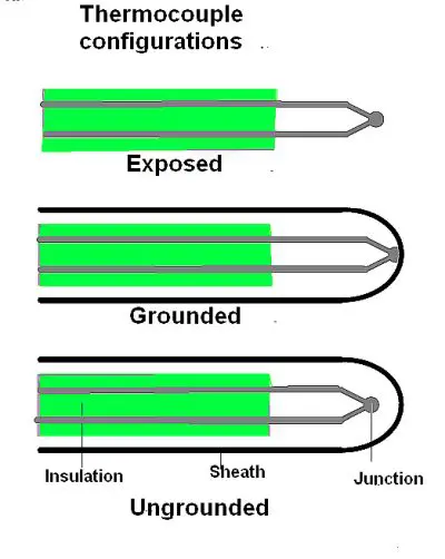 Thermocouple leads are protected by insulation and often incorporate a protective sheath at the junction tip to protect the sensor element. A thermocouple without a protective sheath is called an exposed thermocouple. Eliminating the sheath allows for a small sensor, with direct heat transfer from the measured object. This type of thermocouple also responds quickly.
In a grounded thermocouple, the sensor is welded to the sheath. In this case, the sheath is often metal, which allows for heat transfer but protects against harsh environments. However, the electrical connection between the thermocouple and the metal sheath makes the measurement susceptible to noise from ground loops. Ungrounded thermocouples are isolated from the sheath via a layer of insulation between the thermocouple the measured object. But the isolation layer slows the sensor’s temperature response.
Temperature measurement accuracy and range depend on the type of the thermocouple used and the standard its manufacturer follows. The International Electrotechnical Commission standard outlined in IEC-EN 60584 contains the manufacturing tolerances for base metal and noble metal thermocouples. ASTM E230 describes a parallel standard used in the U.S. from the American Society for Testing and Materials.
Thermocouples show a wide range of error depending on the tolerance class. However, few thermocouples have error tolerances better than ±1°C.
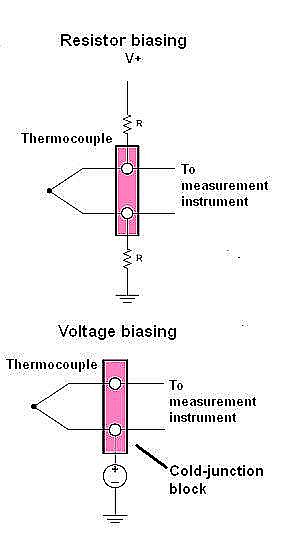 In some measurement configurations, thermocouples require a dc bias voltage to set the sensor operating point. There are several ways to bias a thermocouple. The most common employs two identical large resistors tied to either end of the thermocouple. The opposite end of the resistors then connect to positive or negative voltage supplies. This method sets the thermocouple operating voltage at mid-supply assuming thermocouple voltage is relatively small.
Resistor values generally range from 500 kΩ to 10 MΩ depending on the input current. But if the thermocouple leads are long, then resistor biasing may create an error. Long resistive leads
will react with the bias current to develop a voltage error in the measurement.
Another biasing method ties the negative thermocouple lead to a known voltage source. Use of a voltage source removes the bias current passing through the thermocouple. Only the input current to the measurement instrument remains, which is usually orders of magnitude lower.

Leave a Reply
You must be logged in to post a comment.