In this FAQ, you’ll learn how to know if your test application needs sensing and how to properly wire a power supply to a load.
Calibrating certain sensing circuits, such as those used in electric vehicles (EVs), is critical to get right. An inaccurate calibration of an automotive battery monitoring circuit could, for example, allow excessive discharge of the battery or allow charging to shut down prematurely. This could lead to a decrease in electric vehicle range or cause the battery to discharge to a level that may damage battery cells.
Engineers use programmable DC power supplies to calibrate important circuits. During testing, you need to know the supply voltage to the monitoring circuit with a high level of precision. Unfortunately, even a highly accurate power supply may not apply the programmed voltage to the circuit under test. That’s because of resistance in the lead wires.
As current travels through the lead wires, there is an unavoidable voltage drop. Although the lead wires have very low resistance, a significant load combined with a long wire run will create a non-negligible voltage drop. Because there is a supply wire and a return wire, the error occurs in both, thereby doubling its effect.
That’s why some power supplies monitor the voltage at the load and feed the value of the voltage drop to their control circuitry. To compensate, the power supply increases its voltage. This assures you of an accurate voltage at the circuit under test. Unfortunately, this may not always be the case.
Compensation strategies
Some programmable DC power supplies use two wires to monitor the voltage at their output terminals. This is known as local sensing (local to the power supply). There is another type of sensing, known as remote sensing, which monitors the voltage at the load. It’s similar to making four-wire voltage measurements with a voltmeter. To compare these approaches, this FAQ looks at two hypothetical examples.
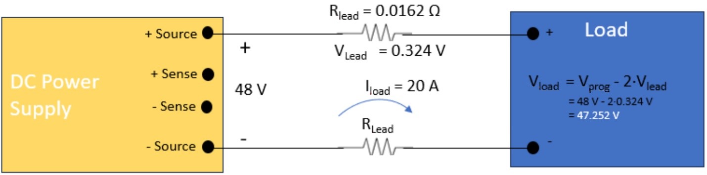
Figure 1 shows a programmable power supply directing 48 V to a load that draws 20 A. In this example, the test leads are standard 12 AWG gauge copper wires covered with typical THWN insulation. The wires have a maximum current rating of 25 A. At room temperature, the resistance is 0.00162 Ω/ft. Assuming the run of wire from the power supply to the load is 10 feet, the voltage drop on each can be calculated at 0.324 V. As there are two wires (supply and return) the total voltage drop is 0.748 V. Although the test engineer set the power supply to output 48 V, the actual voltage to the circuit under test is 48 V – 0.748 V or 47.252 V. This error may seem small, but it is 1.6%, a significant error that is unacceptable for many automotive, military, and avionics applications.
How remote sensing works
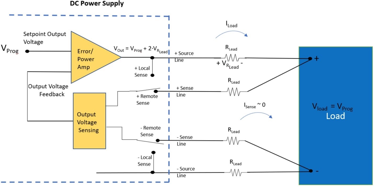
The example in Figure 2 uses the same load circuit but with remote sensing of the voltage drop. Because the remote-sense measuring circuit has high impedance, it draws negligible current from the load. The circuit measures the voltage across the source wires and feeds its value to a control circuit in the power supply. Using that value, the control circuits raise the output voltage until the voltage at the load matches the programmed output voltage. Figure 2 shows how remote sensing eliminates the output inaccuracy caused by the resistance of the lead wires.
Real-world issues
While remote sensing works perfectly in theory, real-world considerations make things more complicated. Back electromotive force (EMF) could damage the programmable power supply’s output stage. This may occur with inductive loads such as motors, electromechanical relays, and solenoids. When de-energized, an inductive load returns stored energy to the circuit. That energy has the opposite polarity of the voltage applied by the power supply. Likewise, charging a battery presents a similar problem. If the power-supply voltage falls below the voltage of the battery, then the battery may discharge into the power supply. Whether the power comes from back EMF or from a battery, it could damage the power supply.
To prevent damage, power supplies are designed with a pair of series diodes. The remote sense circuit also needs protection.
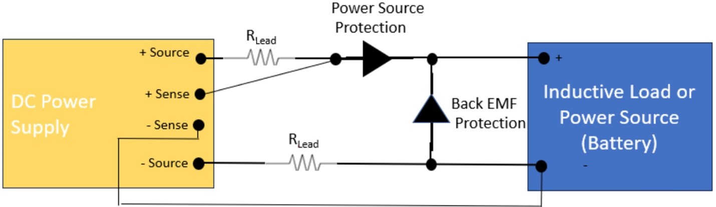
Figure 3 illustrates a practical remote sense wiring design that protects all power-supply lines from unwanted energy. The design isn’t perfect, however, as the + sense lead is no longer at the load, which means it can’t compensate for the voltage drop in the protection diode. To overcome this drawback, power supply designers characterize the voltage drop of the series diode and add that information to the programmed output voltage. The result is that the voltage at the load will be the same as the programmed voltage and that the power supply is protected from damage caused by inductive and power source loads.
Avoid power-supply oscillations
Another issue to design for is oscillation in the power supply caused by noise on the sense lines. The voltage-sensing circuit employs a high input impedance. Non-negligible perturbations will be amplified and fed to the control circuit of the power supply. The noise in the control circuit will create a ripple in the power supply’s output. In the case that the fluctuations are of enough magnitude, the power supply could oscillate, a condition that potentially could damage it and the device under test.
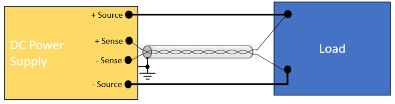
Fortunately, you can avoid this situation by using best-practice wiring techniques. Shield the sense leads to minimize EMI noise. In addition, you can prevent a magnetic field from inducing a voltage by using twisted-pair wire in the loop area of the sense lines. Of course, route the sense lines at a safe distance from the source lines, which could induce a magnetic field. Figure 4 shows the best approach for connecting sense lines from the load to the power supply.
Test with confidence
Assuming that you apply good wiring techniques, remote sensing provides confidence in your tests. The voltage programmed into the power supply will be accurate at the load, which is what you expect.

Leave a Reply
You must be logged in to post a comment.