Optical fiber is actually a waveguide for light and operates in accordance with a principle known as total internal reflection. In contrast to electrical conduction, there is low loss and signals can be conveyed over considerable distances without amplification.
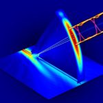
Total internal reflection happens when a propagated wave strikes the boundary between two dissimilar materials, provided that the angle of incidence is larger than the critical angle. Thus, for electromagnetic radiation within a waveguide, and in particular light within an optical fiber, the wave/particle will bounce off the inner surface from side-to-side to proceed downstream through the medium. The phenomenon also arises with much lower-frequency sound waves propagating through water. In oceans, they bounce with minimal loss off the boundaries between ocean layers that are at different temperatures. The phenomenon makes it possible to hear the cries of whales thousands of miles away.
If the boundary is between layers having different refractive indices, the energy will be partly reflected and partly refracted. The proportion depends upon the refractive indices of the materials on either side of the boundary and also upon the angle of incidence. There is near total reflection with little loss when the angle is more nearly parallel than a critical amount with respect to the boundary.
Optical fiber is a special case of a waveguide, optimized to convey light waves. It is small diameter and far less expensive than waveguides that are built to constrain lower-frequency energy. Light waves can be transmitted without losing amplitude because of the inverse square law and capacitive or inductive reactance.
Waveguides for RF frequencies are manufactured as hollow metal pipes, usually rectangular in cross section and having bolted and gasketed fittings where sections join. Waveguides are necessary for carrying microwaves between two points because conductive cable, even coax, greatly attenuates high frequencies because of its distributed capacitive and inductive reactance.
Consider a waveguide associated with the familiar satellite dish antenna. A small electrode sits at the focal point of the parabolic reflector. It re-radiates energy into the waveguide, which conveys it to the low-noise block. There, among other functions, this wave energy is heterodyned down to a frequency where it can be transmitted via coaxial cable to the modem, usually inside the building.
A much more expensive waveguide — so massive that it must be set by means of a crane –carries the output from a large dish-type astronomical radio telescope antenna to an indoor location for processing.
The first optical fiber, introduced in the 19th Century, consisted of a single, flexible strands of drawn glass. The cladding, having a lower refractive index, consisted of the surrounding air. It wasn’t until the 1950s that solid cladding emerged, setting the stage for a more efficient medium that could convey power or data over longer distances.
In 1965, Telefunken Labs in Germany demonstrated a working fiber-optical data transmission system. Soon, optical fiber became a practical communication medium, attenuation dropping below 20 dB/km. For a time it was believed that attenuation was caused by physical processes such as scattering, which in principle could not be avoided. But further research revealed that the use of highly purified silica glass eliminated most medium-distance attenuation.
Today’s optical fiber exhibits far less loss than copper cable of practical diameter. Distances between repeaters in long-haul applications currently approach 100 miles. Optical-fiber engineers have endeavored to realize simultaneous high-data rates and distance between repeaters. Nippon Telegraph and Telephone, a leader in the field, in 2012 succeeded in transferring 1 Pbit/sec over a single 50-km fiber.
Because there is no appreciable heat dissipation, optical fiber can be bundled. And because of its flexibility, long, complex installations are viable. It does not emit nor is it subject to electromagnetic interference, so there is no such thing as crosstalk. Capacitive and inductive reactances are not factors.
Wavelength-division multiplexing lets individual fibers carry many independent channels using light at discrete wavelengths. Optical fiber without conductive armor can be safely used in high-voltage switchgear and in power generating facilities. It is also safe in hazardous areas where volatile flammable liquids and gases are present. In contrast to electrical cable, wiretappers have far greater difficulty tapping into optical fiber.

Optical fiber is classified as multimode or single mode. If the core diameter is greater than 10 μm, it is multimode. Of the two types of optical fiber, multimode is more user-friendly and easier to splice. The large core diameter lets light of different wavelengths pass, but lengths are typically limited to 2,000 feet due to modal dispersion, depending on bandwidth requirements.
Multimode fiber is generally confined to a single building. If a segment of multimode fiber exhibits poor performance — usually because of a kink, over-tightened securing hardware, or other damage during installation — the entire run is often replaced, rather than attempting to locate the fault and splicing in a new piece.
The larger core size of multimode fiber permits the use of LEDs and vertical cavity surface-emitting lasers as light sources. But in multimode, the product of bandwidth and distance is lower. Also, because multiple propagation modes are used simultaneously, modal dispersion is a factor. If splicing becomes necessary, multimode is easier and requires less tooling than single mode.
Lasers that drive single-mode optical fiber produce coherent light that is confined to a single wavelength, so the maximum distance between repeaters is much greater thanks to the absence of modal dispersion. Eventually, single-mode fiber must be terminated or spliced.
Utilities generally subcontract single-mode construction to specialized contractors, who deploy substantial amounts of equipment and workers with the required expertise to complete and test the installations.

The splicing of multimode optical fiber usually employs mechanical connectors, which are also used at the terminations. Single-mode fiber, in contrast, requires fusion splicing. In this process, the two ends to be spliced are first stripped and the jackets removed. Then the ends are cut with a precision cleaver so they are exactly perpendicular. The fusion splicer contains fixtures that hold the ends together so the proposed splice can be inspected on a video screen. A small amount of heat is applied to eliminate dust and moisture. Then additional heat is applied, melting the glass and creating a permanent fusion joint. In the fusing, it is critical that the core and cladding do not mix, and the boundary between them is not compromised.
The splicing equipment then estimates splice loss. Light is directed through the cladding and any light leakage is detected and measured. For field work, single-mode splicing is performed in a temperature-controlled van.

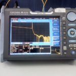
An optical time domain reflectometer (OTDR) measures and displays optical fiber qualities. With flat screen display and front panel controls, it resembles an oscilloscope. Bench-type and hand-held models are available.
The OTDR resembles a time-domain reflectometer, the difference being that it is used with optical fiber.
The instrument applies optical pulses to a segment of optical fiber and receives the reflected pulses. The strength and elapsed time of the received pulses are measured and displayed so the user can locate a discontinuity or fault. The OTDR is indispensible in working with long, concealed or buried optical media.
Figures of merit in an OTDR include resolution, which is a measure of the temporal separation between discernible events. This relates to the duration of the pulse and sampling interval. A shorter pulse duration and data sampling interval mean better resolution. High-amplitude reflections returning to the instrument may temporarily overload the detector, reducing resolution. The instrument recovers after a period of latency. A Fluke Optifiber Pro model includes smart-phone connectivity, and is widely used in on-site fiber certification and end-face inspection.


Leave a Reply
You must be logged in to post a comment.