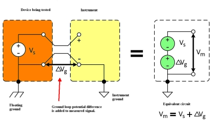
Consider a typical bench-type oscilloscope that connects to the ac outlet. It typically has an equipment grounding conductor that connects to the building’s electrical grounding system. Consequently, it is hazardous to connect the scope probe’s ground return lead to a printed circuit board or electrical equipment terminal or wire that is referenced to and floats above ground potential.
 If you make this connection, there will be smoke and sparks. The best-case outcome is that the thin ground return lead will act as a fuse and clear the fault before damage is done to oscilloscope, equipment under investigation, and user.
No such hazard exists when the voltage referenced to ground does not float above it, which is usually the case. However, it is important to connect the probe tip and ground return correctly. In a ground-referenced circuit, the ground return lead, not the probe tip, must be solidly grounded. Also, it is important that the premises wiring — including extension cords and plug connections — not be crossed anywhere from the circuit under investigation all the way back to the building breaker box. You can verify this by means of an electrician’s inexpensive circuit analyzer or a neon test light.

Some well-meaning individuals try to eliminate the hazard described above by cutting off the ground prong of the oscilloscope’s supply cord. While this eliminates that hazard, it introduces a different even more hazardous situation: If a ground fault occurs within the instrument, external metal parts will be energized to the full utility potential.
What about an electrical source not connected to a grounded power source? It is not connected to grounded power, it does not involve a voltage that is referenced to and floats above ground potential. In this case, there is no possibility of a high current flowing through the ground return lead. An example is a simple 9-V battery that is not connected to any external equipment. If the scope probe tip connects to the positive pole and the ground return lead connects to the negative pole (the usual arrangement), there will be no fault current and the oscilloscope display will consist of a flat horizontal line at the nine-volt level above the X-axis. If the connections are reversed, there is no harm in that. The horizontal line will now be the same distance below the X-axis. Either way, there will be no fault current.
A bench scope equipped with a differential probe can make a floating ground-referenced voltage reading. This configuration displays only the difference between the potentials at the points of connection. Thus, common-mode voltage is rejected.
There are instances, as in variable-frequency motor drives, where both sides of the circuit are referenced to, and float above, ground. These voltages are higher than ordinary utility voltages, so the fault current will be especially hazardous. The differential probe, as long as voltage limitations are observed, works well in these applications.
Many electrical engineers and technicians prefer to use hand-held, battery-powered oscilloscopes. These instruments don’t connect to a grounded power source, so they are not ground-referenced, and the fault current we have been discussing does not appear.
The major oscilloscope manufacturers offer hand-held, battery-powered oscilloscopes. Because they are isolated from grounded mains, they are safe for taking readings with the ground-return leads connected to floating ground-referenced voltages. Some hand-held, battery-powered oscilloscopes have ground-return leads from the separate analog input channels that are isolated and insulated from each other, while others do not. You can check out the manufacturer’s documentation and/or use an ohmmeter to verify the status of the ground leads.
Because hand-held oscilloscopes are of necessity smaller and more compact than bench models, the readability of the display may be limited. And their compact size prevents these scopes from carrying some of the advanced features seen in the larger and more expensive bench-tops. Overall they are satisfactory and serviceable alternatives, with the advantages of portability and ability to take hazard-free floating readings.
Here’s a rundown of some outstanding hand-held, battery-powered oscilloscopes:

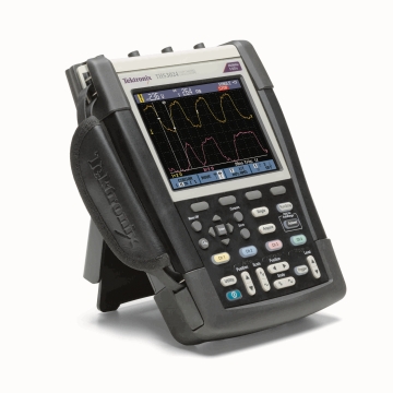
Tektronix THS3024 hand-held, battery-powered oscilloscope — This scope is unusual for a portable instrument in that it has four channels. Specifications include an impressive 200 MHz bandwidth and 2.5 GS/sec sampling rate.
Pressing acquire, the waveforms options tab appears at the bottom. Glitch, acquisition and averaging (on or off) appear, but what is really interesting is the waveform menu, which offers selections for normal, persistence, mathematics and reference. These are features found in the most advanced bench-type oscilloscopes.
It’s worthwhile to use the arrow keys to scroll over and down to highlight mathematics. Then press enter. Function options are add, subtract, multiply, XY-mode and FFT (Fast Fourier Transform). Source A and Source B are shown. The default is channel one for Source A and channel two for Source B. These can be changed by scrolling over and down. Make any desired changes and press enter.
XY-mode permits voltages to be fed into the channels that are selected for Source A and Source B. Source A is displayed, and triggering takes place in response to Source B. The displays are highly instructive lines, circles and ellipses that are known as Lissajous figures.
Scrolling back and down to FFT, Source B disappears because there is a single source only. Available windows are auto, hamming, hanning and none.
When an ac voltage is used as the source, a frequency domain version displays. The Y-axis as always scaled to represent amplitude. The X-axis, rather than showing time as when displaying a conventional waveform, now is scaled to represent frequency. Accordingly the various harmonics of a non-sine wave are shown with the amounts of power expressed in decibels.
The Tektronix THS 3024, like bench models, has a USB slot. It will accept a flash drive in which waveforms can be saved, then subsequently displayed in a computer. There is also the option to save waveforms in and recall them from internal memory.

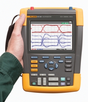
The Fluke 190-502 ScopeMeter is another outstanding hand-held, battery-powered portable oscilloscope. (Fluke and Tektronix are currently owned by the same parent company, Danaher Corp.) This scope has two rather than four analog input channels, but these are sufficient for almost any application where a portable instrument would be used. Apart from the number of channels, the Fluke ScopeMeter has noteworthy specifications. The bandwidth is 500 MHz with a 5 GS/sec sampling rate, sufficient for most electronic work.
The Fluke Scopemeter has a remarkably bright, clear display and a highly readable human interface. The front panel and many of the features, notably mathematics, are similar or even identical to those of the Tektronix THS3024. Besides being a portable oscilloscope, this instrument is a well-appointed multimeter. Three prominent buttons at the left side of the display are labeled, starting at the top, scope, meter and recorder.
Pressing scope, the display shows a standard setup for time-domain readings of two electrical signals connected to the analog channel inputs. In this mode, the instrument functions as a portable oscilloscope much like the Tektronix instrument described above. The inputs are fully isolated and insulated from the premises electrical ground, permitting safe floating measurements.
When the middle button, meter, is pressed, the instrument becomes a fully functional multimeter.
On the top panel are two ports, separate from the oscilloscope inputs, that accept multimeter probes, color-coded red and black, supplied with the instrument.
Pressing F1, currently associated with measure, the various meter modes are shown:
• Ohms
• Continuity (with audible beeps)
• Diode
• Temperature (requiring a specialized probe)
• Volts AC
• Volts DC
• Volts AC + DC
• Amps AC
• Amps DC
• Amps AC + DC
Pressing the recorder button, three menu items appear. They can be highlighted by means of the down arrow button, and opened by pushing enter. The three menu items are:
• Trend plot meter, which plots a graph of selected meter measurements over time
• Trend plot scope, which plots a graph of selected scope measurements over time
• Scope record, which records scope waveforms in deep memory.
Opening the last of these, we see how the recorder function can be used to record waveforms as accessed through one or both channels, and how after the recording has been stopped, these waveforms can be viewed.
Like the Tektronix THS3024, the Fluke ScopeMeter has a USB slot and a save button, so waveforms can be saved and later be imported into a computer where files can be saved, printed or emailed.

Why doesn’t it matter if the circuit ground floats below earth?