The oscillator is a critical component of many types of electronic equipment. Transmitters are one obvious example of a critical application, but virtually all receivers — including TV’s, operating on the superheterodyne principle — mix a local oscillator with the radio-frequency (RF) signal to produce a more manageable intermediate carrier wave.
Other oscillator applications include radiation therapy, music synthesizers and digital clocks.
Of course, both waveform integrity and frequency stability are necessary for successful oscillator operation. Besides component aging and sudden trauma, thermal effects are a principle cause of poor oscillator performance. Equipment designs can incorporate active cooling, shielding and spatial separation to counter heat rise.
Oscillators like to see a high-impedance load for optimum reliability, so this factor should strongly influence over-all equipment architecture. Where it is not necessary to change frequency during the ordinary course of operation, a quartz crystal can be used rather than a resonant LC circuit. The quartz crystal, due to its piezoelectric properties, will ring at a relatively uniform rate as long as temperature doesn’t vary too much. For highly critical applications, low-heat ovens are used so there is little temperature variation.


Examples of crystal oscillators are the Pierce circuit, Reinartz circuit and the variable frequency crystal oscillator. Conventional oscillators with electronic resonant frequency circuits employ various combinations of coils, capacitors and solid-state devices to create wave action.

an output voltage proportional to the phase error of the two signals. This output voltage passes through the loop filter and then is an input to the VCO which controls the output frequency. This self correcting
technique forces the output signal to be in phase with the reference signal. When both signals are synchronized the PLL is said to be in lock condition. The phase error between the two signals is zero or almost zero at this point.
The phase-locked loop (PLL) frequency synthesizer has a programmable divider, phase comparator and reference oscillator. This arrangement permits the output of a voltage-controlled oscillator (VCO) to be divided by an integer so as to output an array of frequencies. If there is frequency drift, the phase comparator produces a dc error voltage. This feedback loop stabilizes the VCO frequency.
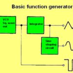
Audio frequency (AF) oscillators are the source of various chimes, beeps and wails that are so much a part of everyday life – everything from an ambulance siren to children’s toys that play musical tunes. A common setup is to use a resistance-capacitance circuit to generate the tone. Distinctive sounds can be produced by varying the amplitude of the harmonics that are part of all waveforms that are not perfect sine waves.
An IC widely used over the years has been the 555 relaxation oscillator. When the device receives a trigger input, the output goes high and remains so until the threshold input is heated up, whereupon the output goes low. To activate the trigger, apply a voltage that is one-third the power supply voltage, and to activate the threshold, apply two thirds the supply voltage.

The 555 in the astable mode will output a nice clean square wave. A 555 operating at slow speeds is often what makes all those blinking lights in our homes. At high speeds it works as a logic clock. At intermediate speeds it is an audio oscillator. In bistable mode, because of the latching action, it makes possible synthesis of a bounce-free switch.

Leave a Reply
You must be logged in to post a comment.