The high frequencies involved in 5G will force a re-think of how to go about characterizing circuits and systems.
Adnan Khan | Anritsu Co.
Engineers responsible for designing and manufacturing 5G chipsets, devices, and systems have more than enough challenges. From a technical standpoint, they must deliver high bandwidth, low latency, and other performance benchmarks. They also
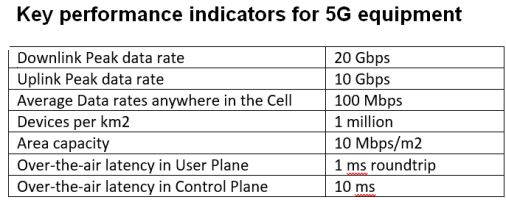
must meet the corporate business case for 5G – cost and profitability. So they must efficiently verify products according to the 3GPP Release 15 specifications to meet key performance indicators (KPIs) in the most timely and economical manner possible.
Test instruments will be important in reaching these goals. Test solutions must address the requirements of measuring present-day 5G signals yet have the flexibility to meet future versions of the 3GPP specifications as they continue to advance.
Developing test processes
Compared to 4G LTE, 5G technology brings greater capacity, lower latency, and a more uniform user experience. No universally approved 5G test standards have been adopted — test specifications are evolving. But 5G testing parameters have a much stronger foundation than was the case with LTE, thankfully. Test companies have worked with customers to determine likely 5G test processes and procedures. Additionally, leading test equipment manufacturers have made accelerated contributions in the development of 5G 3GPP specifications, not the case in early stages of 4G.
The result is a consensus in the industry about the likely specifications for the first phase of 5G New Radio (5G NR), also known as 3GPP Rel-15. Based on all this data, guidelines have been established to help test vendors introduce solutions that help engineers develop accurate models, thereby expediting the design process and controlling the cost-of-test.
The key aspects engineers must address to successfully launch
5G include:
Antenna and device design
Beamforming/millimeter wave (mmWave)
Price and time
Present-day LTE mobile terminals have several built-in antennas which can be physically connected to test equipment; 5G terminals could have a significantly higher variety of antennas. The 5G device has LTE antennas as well as 5G antennas, and 5G antennas may include an array of antenna elements. In 5G mmWave applications, high-gain, steerable phased array antennas will be used to overcome high propagation loss.
Adding to the complexity is that mmWave antenna arrays are embedded in the chip of a 5G mobile device which makes it impossible to test with a physical connection. Implementing a measurement connector for each antenna would boost the mobile/terminal size and contradict cost-reduction trends. And use of cable would also increase signal loss. All these factors make it significantly more challenging for engineers to verify antenna performance.
The testing of 5G antennas employs Over-the-Air (OTA) measurements, including power and sensitivity. OTA and interoperability testing ensure the mobile device performs according to 3GPP 5G NR specifications by simulating 5G NR technologies in a real-world environment across a broad set of use cases and deployment scenarios. These tests take place in low-band spectrum below 1 GHz, mid-band spectrum such as 2.5 GHz, 3.7 GHz to 4.2 GHz, as well as the 28 GHz and 39 GHz mmWave bands.
To control test costs, engineers must decide which tests must take place in an OTA chamber. Chipset/device manufacturers and carriers all must agree on an acceptable margin of error for certain performance parameters to eliminate the need for some OTA tests. For example, there are a considerable number of protocol tests. Because the verification of the protocol stack does not require RF measurements, protocol testing may take place without a chamber.
The measurement of RF parameters in the mmWave range requires simultaneous OTA antenna measurements. Signal analyzers must be able to accurately test parameters that include Effective Isotropic Radiated Power (EIRP), Total Radiated Power (TRP), and Effective Isotropic Sensitivity (EIS).
Most OTA antenna measurements should take place either in the far field or in a computationally simulated far field. The far-field distance rises with frequency and drops with antenna size. For example, at 28 GHz, the far field distance begins at 34.2 cm whereas at 39 GHz it begins at 24.5 cm. Antennas must also be calibrated at mmWave frequencies to ensure accurate directivity and beam width, as well as phase and gain.
Conventional OTA tests on mmWave designs can be costly. Traditionally, they require two test chambers – the reverberation chamber and the more-expensive anechoic chamber. Studies indicate that better results on mmWave designs come from conducting far-field measurements (FFM). That implies measurements taken 1.5 – 2 m away from devices supporting 28 GHz. Such testing will require a significant additional investment, considering RF measurements at LTE frequencies could take place in conducted mode.
A second testing method is to develop FFM conversions or reflection parameters. Using this approach, engineers can conduct near-field measurements (NFM) and use industry-accepted algorithms to transform them to FFM.
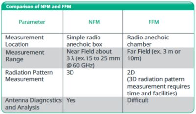
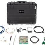
An NFM application can employ compact mmWave measuring instruments and the radiation pattern can be measured using a simple radio anechoic box in a room. This approach eliminates the high cost and long configuration time associated with measurements in a large radio anechoic chamber.
OTA measurements are necessary for other reasons as well. With 4G UE, the transceiver and antenna are separately evaluated. In 5G mmWave, the introduction of high frequency and massive MIMO force the transceiver and antenna to be tightly integrated, making it difficult to evaluate each separately.
Verifying that 5G devices conform to specific feature sets is another consideration. The focus today is on relatively simple capabilities — two-component-carrier (2 CC), carrier aggregation (CA), for example — but 5G equipment will quickly ramp up to higher bandwidths with more carriers. This scenario is one reason why engineers need test solutions that support up to eight component carriers (8 CCs) in a single instrument.
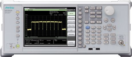
Again, a signal analyzer will be the instrument of choice to test 5G device performance. Among the RF tests that must take place with a high degree of accuracy are frequency power, EVM, and spurious emissions. These tests require a signal analyzer with a high dynamic range as well as extremely flat amplitude and phase.
Though the emphasis today is on 5G NR, beamforming and other mmWave applications are not far behind. These higher-frequency 5G designs create special test factors, as engineers must conduct static tests on devices and antennas in active beamforming environments. Engineers need to determine how many points are necessary to obtain measurements, trading off measurement accuracy for an acceptable verification time/cost of test.
One of the most important tests on mmWave devices is propagation loss. Signal power at mmWave frequencies can drop significantly from path loss caused by environmental conditions, much more so than the path loss experienced at traditional frequencies (i.e., ≤ 6 GHz). At 28 GHz, the path loss is approximately 40 dB higher than at traditional LTE frequencies. This is considerable because the received power at the far end of the link is halved for every 3 dB of path loss. Engineers need test solutions that can conduct this critical measurement with a high degree of accuracy.
Cost-of-test and time-to-market
Engineers designing and manufacturing their chipsets and devices have more to consider than the complexities associated with 5G. Test solution companies must work with customers to develop environments that minimize costs. Test times are important at sub-6 GHz, but their importance will be compounded at mmWave frequencies where the tests inherently can take significantly longer.
In response, test solutions will need to be built on flexible platforms that facilitate upgrades of current solutions. This approach allows engineers to protect their investments in existing test solutions and economically upgrade to 5G. It also saves time because engineering staff needn’t learn new instrument controls, operations, and test cases.
Software will also play a key role in 5G testing. With appropriate software, a single instrument can verify 5G NR, as well as LTE, LTE-Advanced, and other legacy technologies, saving time and money. Future standards can be addressed with software rather than via purchasing more expensive hardware.
In a nutshell, 5G presents several test challenges for engineers, ranging from higher frequencies and performance expectations to more complex designs, time and cost pressures. Test instruments having flexibility and reliability will bring the efficiencies needed to meet current requirements and evolve as 5G advances.


what are the 5G field measurement parameters on signal level and quality level. massive MIMO and beam forming