Engineers have several mmWave over-the-air test methods available for evaluating phased-array antennas used in antenna-in-package designs. Each has pros and cons.
5G bought mmWave frequencies from 24 GHz to roughly 50 GHz to cellular networks. Those frequencies provide wide bandwidths that enable high data rates. Unfortunately, signals at these frequencies are susceptible to atmospheric absorption, scattering, and blocking. To offset these problems, mmWave depends on phased-array antennas and beam steering to direct energy to the target. Antenna-in-package (AiP) designs combine antennas with modems and mmWave components. That saves space but eliminates test points, making wired testing impossible.
Testing AiP designs require over-the-air (OTA) techniques.
Evaluating antenna characteristics such as gain, phase, and radiation patterns guarantees beam-steering performance through OTA radiation testing is crucial to ensure that these systems meet the required standards for performance, coverage, and reliability.
OTA measurement methods include phased-array, far-field, indirect far-field, and horn antenna techniques. Testing AiP RF front-end systems emphasize the importance of calibrating and measuring gain loss and phase error, which directly affects beamforming performance.
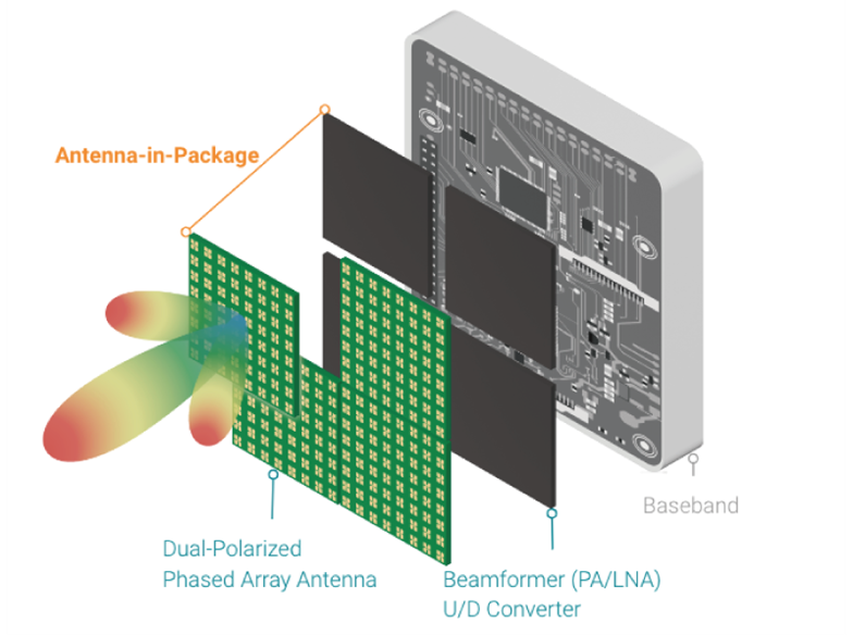
Figure 1. An antenna-in-Package system architecture consists of a modem, transceiver, beamformer, and antenna.Figure 1. An antenna-in-Package system architecture consists of a modem, transceiver, beamformer, and antenna.
Figure 1 shows an RF front-end module with an integrated antenna array and beamformer ICs that form an active phased array beamforming subsystem consisting of:
- phase shifters,
- a power amplifier (PA),
- low-noise amplifier (LNA), and
- optional integrated frequency up/down converters, power management, and control.
Phased arrays control a signal’s gain and phase, creating constructive and destructive interference that enables beamforming and beam steering, as shown in Figure 2. AiPs are used in 5G/SATCOM applications.

Figure 2. Altering a signal’s gain and phase creates beamforming and beam steering.
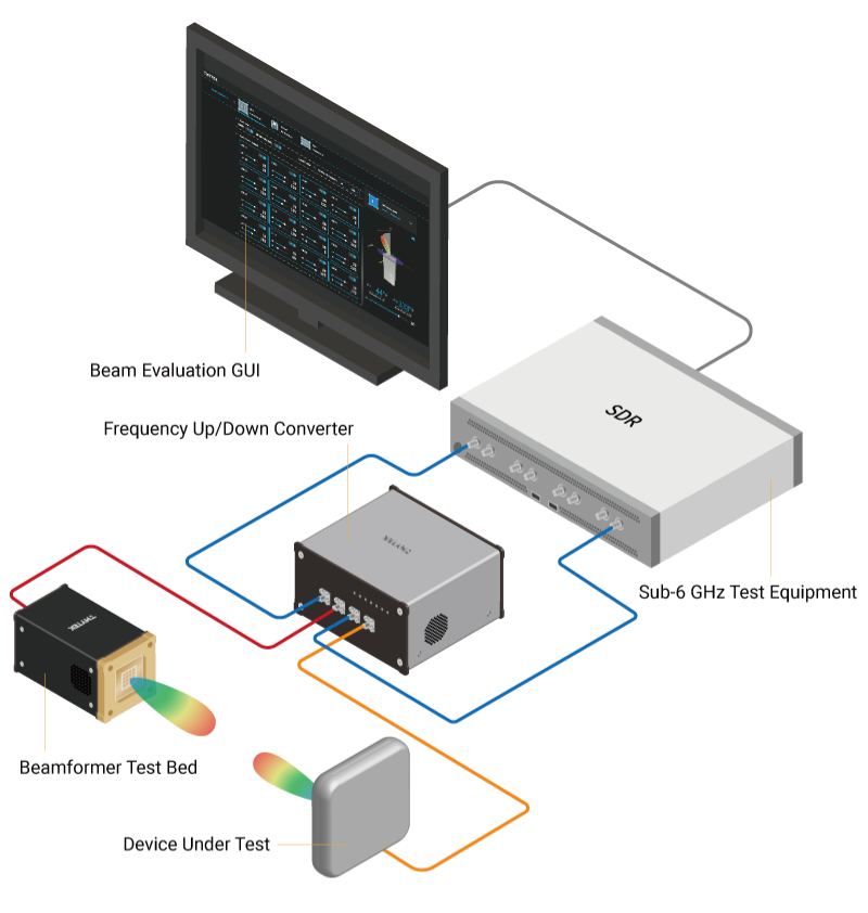
Figure 3. Generic beamforming test architecture uses an up/down converter and software-defined radios.
Figure 3 shows a test bed for evaluating beamforming characteristics, algorithms, and other advanced experiments such as MIMO and channel sounding.
Far-field testing
Far-field testing is a commonly used method for 5G mmWave OTA testing. It involves measuring the electromagnetic radiation emitted by the device under test (DUT) at a distance greater than one-tenth of the wavelength of the signal being transmitted; refer to Figure 4. The far-field region is typically defined as the region beyond the Fresnel zone, which is the region surrounding the device where the phase of the electromagnetic waves is not uniform. Far-field testing is typically performed using an anechoic chamber, a specially designed room that absorbs electromagnetic waves to eliminate reflections from the walls and floor. The main advantage of far-field testing is that it provides a true representation of the antenna’s radiation pattern.
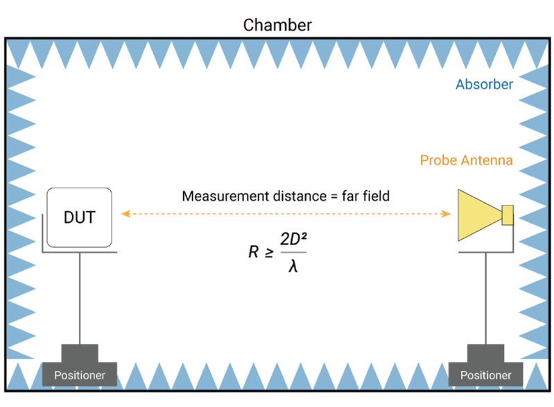
Figure 4. A far-field testing takes place at a distance (D) that’s at least 1/10 of signal wavelength.
Another form of testing called compact antenna test range (CATR) is a type of indirect far-field testing; a measurement method used to evaluate an antenna’s performance in a compact and controlled environment. It involves measuring the electromagnetic radiation emitted by the DUT at a distance greater than one-tenth of the wavelength of the signal being transmitted but not in the far-field region. See Figure 5 for the environment setup. Indirect far-field testing is typically performed using a reflector or lens to focus the electromagnetic waves emitted by the DUT onto a detector. This method can be less expensive and easier to set up than traditional far-field testing, but it may not be as accurate. CATR is typically used to measure the radiation pattern and gain of an antenna, as well as to evaluate the performance of beamforming algorithms.
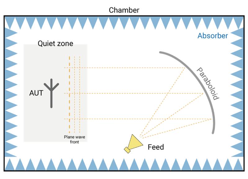
Figure 5. An indirect far-field test uses a reflector to focus electromagnetic energy from an antenna.
Horn-antennas used for testing the radiation pattern of an antenna measures the field strength at the aperture of a horn antenna, as shown in Figure 6. This method is useful for testing arrays of antennas because the horn can individually illuminate each element of the array. Unfortunately, you need several horn antennas, resulting in increased cabling complexity. The main advantage of horn testing is that it allows for easy isolation of individual elements in an array. Horn testing may not, however, provide as accurate a measurement of far-field radiation pattern representation for the antenna as far-field or indirect far-field testing.
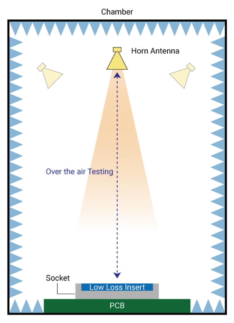
Figure 6. Horn testing setups use more than one antenna.
Challenges of AiP measurement
When testing the performance of AiP RF front-end systems, you must calibrate the test bed and measure gain loss and phase error to ensure that the beamforming performance is up to standard. Gain loss is the difference between the expected and actual gain of an RF system, and likewise, the phase error is the difference between the expected and actual phase of an RF signal. Calibrating and measuring these parameters is crucial to ensure that the beamforming performance of an AiP RF front-end system is consistent and reliable.
Figure 7 is the experiment of a 1×4 AiP module where the power gain is turned off or turned down, and the phase difference between channels is adjusted. What if it only measures the peak gain (gain at zero degrees)? It would not be able to absolutely justify the difference due to it being under the testing tolerance, which could result in extra troubleshooting effort. Instead of checking and comparing the beam pattern in red (all channels open for good results) and blue (defect sample), there are clear results that make it easy to identify defects by the beam pattern.
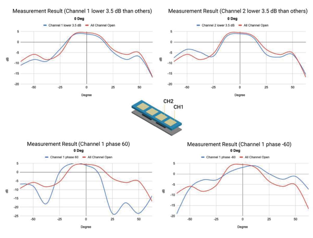
Figure 7. AiP gain-loss and phase-error failure analysis experiment shows differences in beam patterns.
Table 1 compares industry standard measurement methods.
| Pros | Cons | Conclusion | |
| Far-field Testing |
|
|
✔ Market proven measurement method for antenna gain and directivity. ✖ Requires larger testing space and is costly. |
| Indirect Far-field Testing — CATR (Compact Antenna Test Range) |
|
|
✔ Alternative measurement method with compact testing space. ✖ Slow measurement speed and is costly. |
| Horn Testing |
|
|
✔ Ultra cost-effective measurement method that is widely produced. ✖ Less testing coverage.. |
In summary, existing chamber-rotator-based measurement solutions provide complete measurement parameters, but they take up significant space and are expensive. In addition, turntable and rotator pattern measurement mechanisms are slow to generate results. Furthermore, although horn testing requires minimal investment for production testing, it evaluates peak only, making it not ideal for identifying defects in phased-array antennas.
OTA testing methodology research
As the mmWave market grows and the demand for phased-array antenna simulation and measurement validation increases, there are various methodologies proposed from both academic research and industry in-house experimentation. Note that pattern-based measurements should be crucial to guarantee beamforming performance from a phased-array antenna.
Research in cost-effective measurements
Gain and phase are key factors in beamforming and beam steering. The only test case to guarantee phased-array antenna performance is a pattern-based measurement. That means the measurement system should contain multiple detecting probes to detect gain power at specific angles. But how to define resolution versus cost is a design topic based on usage needs.
Because peak gain is detected only by a single horn antenna, what if the system incorporates multiple horn antennas and is placed as the sector to detect the gain from different angles? It is thus possible to redraw the gain chart into a “pattern” map. The consequence of horn array methodologies is the beam pattern resolution corresponds to the quantity of horn detection sources. Higher pattern resolutions mean larger horn arrays, which increases cost. When there are many horn detectors in the same measurement system, calibrating each antenna for consistency is also challenging.
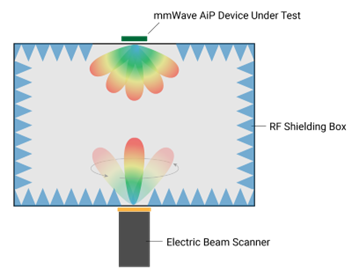
Figure 8. This testing concept uses an electric beam scanner in an RF shielded box.
As an alternative to using horn antennas, a well-calibrated AiP system could be used as an electric beam scanner and activate beam-to-beam measurements to detect each beam angle from the DUT. The entire system would ideally be contained inside a chamber box to avoid interference (see Figure 8 for the system concept). Because software controls beam switching and the time delay when switching is mere microseconds, by theory, a full 3D pattern measurement could be generated within 10 sec. This 3D beam pattern measurement methodology is worth continued development and validation.
Near-field to far-field
Measurement space correlates to the frequency and diameter of the antenna, and the only way to minimize space is with near-field testing. The problem: there is no radiation behavior associated with the near-field region, hence the essential need for NF-FF (near-field to far-field) transformations.
NF-FF calculations should be calibrated and defined in a certain test configuration and chamber environment. Although there are several approaches to transformation equations that result in proven information mapping, there is ample research and experimentation available for review online, so it will not be discussed here in depth.

Figure 9. Failure analysis performed by a software AI engine shows measured results compared with “golden” results.
To accelerate failure detection, you can use AI software to process large amounts of test data into a characteristic model for pattern recognition. You should analyze beam patterns in real-time to identify failures where defective components could be dispatched using conditional configurations. With such high-speed testing, you can collect measurement results quickly. Doing so lets you build a comprehensive database rich enough to develop AI modeling for advanced intelligent analysis, such as the characteristic comparison of gain and error-vector magnitude (EVM) maps in Figure 9. This approach lets you correlate production batches with characteristics of array elements to significantly improve production efficiency while providing valuable feedback to design engineering teams.
Applying outside-the-box thinking and combining all the above testing methodologies could create a useful OTA testing method that addresses testing speed as well as increases test coverage. As cost is always a key investment consideration, total cost of ownership (TCO) optimization could incorporate a simplified setup with electric scan and AI automation.
5G mmWave OTA testing is an essential process that plays a critical role in the development and deployment of 5G mmWave systems, which operate at frequencies above 24 GHz and offer higher data rates and lower latencies compared to lower frequency bands. OTA testing lets engineers evaluate the performance of mmWave systems under real-world conditions, including the effects of multipath, reflections, and penetration loss. The most important factors are beamforming performance, which is identified by the beam pattern through the gain and phase measurement, and testing speed that launches mmWave from production to commercialization to innovate the marketplace.