In 1895 William Roentgen observed X-rays although he could not explain their mechanism. The following year Henri Becquerel demonstrated that certain compounds of uranium emitted radiation that resembled X-rays. He showed this activity differed from the phenomenon of phosphorescence. The radiation seemed to be emitted continuously from the uranium. Did this violate the well-known principle of conservation of energy?
The answer to this question is no. With the emission of radiation the substance decays into another element or isotope, fulfilling the previously discredited dream of the alchemists. Describing and quantifying this process became Marie Curie’s life work.
Curie’s work took place prior to 1903. Interestingly, she didn’t use a Geiger counter to describe or quantify radiation. That instrument used a Geiger–Müller tube that wasn’t invented until 1928. Previously, Curie’s husband Pierre with his brother had improved an instrument that was known as an electrometer. The new version was capable of measuring small amounts of electric charge. Marie Curie found that this meter would detect the presence of electric charge in the immediate vicinity of radioactive material because radiation was ionizing the surrounding air, creating charge carriers. She soon found that this phenomenon was a function of the amount of radioactive uranium at the location. The conclusion was that radioactivity was not due to the chemical reaction of a compound, but instead arose from nuclear activity of the actual atoms. At this point in time the previous belief in the indivisibility of individual atoms was overturned.
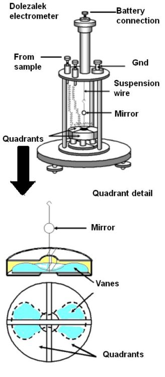
Electrometers could be operated in several ways but the most common method was to measure the rate of deflection of a vane suspended by a fine wire or fiber. The potential being measured turned a butterfly-shaped vane. The magnitude of this deflection was related to the potential (or charge). The rate of the deflection was related to the current.
Early electrometers weren’t sensitive enough to detect the charges Curie was interested in. That changed with the invention of the Dolezalek electrometer which contained thin and light vanes, sometimes made of metal-coated paper. One end of a short rigid wire was connected to the middle of the vane while the other end of the wire had a small hook. The backside of a tiny mirror (a few millimeters in diameter) was attached roughly half way up the wire. The hook was connected to the end of a thin flexible wire or fiber so the vane and mirror could rotate.
The vane itself was inside, but didn’t touch, a metal enclosure divided into four quadrants. Each quadrant was electrically connected to the quadrant diagonally opposite so they had the same charge. One pair of quadrants had a positive charge, the other pair a negative charge. If the potential difference between the vane and the quadrants changed (caused by current from the ion chamber), the vane and the mirror rotated.
To determine the position of the vane, a beam of light beamed through a window in the electrometer case reflected off the mirror onto a scale. As the current from the ion chamber changed the potential difference between the vane and the quadrants, the vane rotated and the reflected light beam moved across the scale. The time to move across a specified number of divisions on the scale could be related to the activity of the sample by calibration with a known source.
The Dolezalek electrometer improved on earlier versions of quadrant electrometers by virtue of more sensitivity. Besides using lighter vanes, its quadrants were smaller and the mirror and vane were suspended by a metal-coated quartz fiber rather than a phosphor-bronze strip. It also eliminated a Leyden jar beneath the quadrants used to maintain a charge on the electrometer vane.
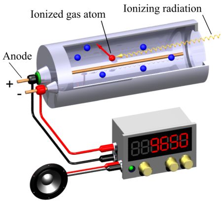
Like electrometers, Geiger counters detect ionization. A Geiger counter has two main parts: a sealed chamber filled with gas, and a display. Radiation enters the chamber and collides with the gas. The collisions push electrons away from the gas atoms and create ion pairs. A wire in the middle of the tube attracts electrons, creating other ion pairs and sending a current through the wire. Electronics translate the current into a display of radiation.
Specifically, the sealed chamber is called a Geiger–Müller tube. The gas is an inert gas such as helium, neon, or argon. A high voltage (typically 400-900 V) is applied to the tube which briefly conducts electrical charge when a particle or photon of incident radiation makes the gas conductive by ionization.
The tube amplifies ionization via the Townsend discharge effect–the formal name for the phenomenon where free electrons are accelerated by an electric field, collide with gas molecules, and free up more electrons avalanche style. The resulting large pulses from the tube are relatively easy to measure.
A point to note is that the output pulse from a Geiger–Müller tube is always of the same magnitude regardless of the incident radiation energy. So the tube cannot differentiate between radiation types. In addition, the tube cannot measure high radiation rates because a “dead time” follows each ionization event. Incident radiation does not cause a count during the dead time. So measurements of high radiation rates can be inaccurate.
Geiger counters can detect gamma radiation and X-rays but with low efficiency compared to alpha and beta particles. For high energy radiation the tube relies on interactions with the tube wall, usually a high Z material such as chrome steel. A variation of the Geiger tube is used to measure neutrons. The gas used is boron trifluoride or helium-3, and a plastic moderator is used to slow the neutrons. This creates an alpha particle inside the detector so neutrons can be counted indirectly.
Most people associate the term “Geiger counter” with a hand-held survey type meter. But area gamma alarms for personnel protection and process measurement applications also use the Geiger principle. There is also a type of gamma instrument known as a “hot spot” detector which locates the detector tube on the end of a long pole. These measure high radiation gamma locations while keeping the operator at a hopefully safe distance.


Leave a Reply
You must be logged in to post a comment.