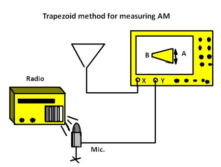
In amplitude modulation (AM), the amplitude of a carrier wave whose frequency remains constant changes in response to the modulating signal. In frequency modulation (FM), it is the frequency of the carrier that varies with the amplitude of the modulating signal. The carrier frequency deviates more when the modulating signal amplitude is higher. There are two important consequences. Because noise is characterized by large amplitude variations, it impacts AM transmission to a greater degree than FM transmission, giving FM a higher signal-to-noise ratio. FM transmission, however, requires greater bandwidth, which in today’s crowded FM spectrum, may be seen as a liability.

AM and FM are two widely-used analog modulation methods. Others are phase modulation (PM), quadrature amplitude modulation (QAM), space modulation (SM) and single-sideband modulation (SSBM).
Phase modulation, like frequency modulation, is a form of angle modulation. In FM the frequency of the carrier varies to signify changes in amplitude of the modulating signal. In PM it is the phase of the carrier wave that is varied. Here again, frequency and amplitude of the carrier remain constant.
The phase of a propagated wave with respect to another propagated wave refers to the relative difference in their instantaneous values in time, as represented by positions on the X-axis of an oscilloscope display when the instrument is operating in the time domain. If successive waveforms are time-shifted in that way, information can be conveyed.
Common applications for phase modulation are Wi-Fi, the Global System for Mobile Communications (GSM), satellite television, signal and waveform generation in digital synthesizers, and phase distortion in sound synthesizers.
Quadrature amplitude modulation appears as a scheme for information encoding in both analog and digital modulation. In both modes, two analog signals or two digital bit streams are conveyed by modulating the amplitudes of two simultaneous carrier waves. In the digital domain, amplitude-shift keying is used while in the analog domain it is amplitude modulation that is operative.
The two carrier waves, which are of the same frequency, are in a quadrature relationship, or orthogonality, which is to say that they are 90° out of phase. Accordingly, they can be demodulated. QAM is used for Wi-Fi and for optical fiber signal transmission. The sender and receiver must have accurate clock signals in common. If they do not maintain synchronicity, the signals lose resolution and are subject to crosstalk. To avoid this corruption, a burst subcarrier is typically included. An example, in NTSC TV transmission, is the color burst.
Space Modulation (SM) differs from the types discussed above in that its purpose is not to facilitate transmission between transmitters and receivers, but rather to aid aircraft in modeling surrounding spaces to help land safely. Demodulation takes place in the space between an aircraft and its intended touchdown location rather than within the instrumentation. Multiple antennas fed with diverse signals create discrete depths of modulation, from which is derived the required positional information.
In SM, carriers at 110 MHz and 330 MHz are modulated by 90 Hz and 150 Hz tones. These signals are conveyed from runway to aircraft to facilitate accurate landing.

Single-sideband (SSB) modulation, also known as single-sideband suppressed-carrier (SSB-SC) modulation, has been used since the first decades of radio transmission to convey information using reduced power and bandwidth. Conventional amplitude modulation concerns itself with an output signal that is twice the bandwidth of the modulating signal. Accordingly, one-half of an AM transmission is eliminated in SSB modulation by suitable filtering with no loss of information; dual sidebands are essentially redundant. The downside and reason SSB is not used universally is the more complicated circuitry at the transmitter and tuning problems at the receiver.
Despite its greater efficiency and lower bandwidth requirements, SSB is not used for broadcasting. Frequency stability and selectivity are beyond the capability of inexpensive receivers. But SSB is justified in point-to-point communication where more advanced receivers are the norm and can be modified as needed.
SSB was first patented in 1915 and used successfully in a 1920s radio-telephone link between New York and London. Telephone companies in the 1930s used SSB over long-distance lines in conjunction with frequency-division multiplexing (FDM).
FDM is a basic form of multiplexing which, as the name implies, consists of conveying two or more signals simultaneously through a link. In its simplest form FDM frequencies have non-overlapping bandwidths, so they can be selected at the receiver using ordinary filtering techniques.
Multiplexing is a generic term meaning that multiple signals are sent through a single conductor without mutual interference. SSB lends itself to FDM because one sideband is not part of the transmission, so the modulated carrier occupies only one-half the conventional FM bandwidth. So twice as many multiplexed signal can be transmitted.

Frequency modulation is also used to convey digitized data. This is done by shifting the carrier frequency among various frequencies that represent digits. In a typical implementation, one specified frequency represents 0 and another represents 1. This is frequency-shift keying (FSK) and it is used in fax and other modems, for Morse Code and in radioteletype. Other varieties of modulation adapted for digital communication are ASK, APSK, CPM, MFSK, MSK, OOK, PPM, PSK, SC-FDE, TCM and WDM:
- Amplitude-shift keying (ASK) is a variety of AM that varies the amplitude of a carrier wave to denote 0 or 1.
- Asymmetric phase-shift keying (APSK) conveys digital information by modulating amplitude and phase of the carrier.
- Continuous phase modulation (CPm0) is used in wireless modems. Rather than the carrier phase resetting to zero at the start of each symbol, the carrier phase is modulated continuously. CPM is characterized by high spectral and power efficiency.
- Multiple frequency-shift-keying (MFSK) resembles FSK, but more than two frequencies are used.
- Minimum-shift keying (MSK) rather than using square pulses, consists of half sinusoids to encode each bit.
- On-off keying (OOK) denotes digital voltage levels, i.e. zeros and ones, by the presence or absence of the carrier wave.
- Pulse-position modulation (PPM) denotes digital bits by transmitting single pulses in shifting positions.
- Phase-shift keying (PSK) denotes digital bits by modulating the phase of the carrier wave. It is used for LANs, RFID and Bluetooth protocols.
- Single-carrier FDMA is a frequency-division multiple access format. It assigns multiple users to a single communications channel.
- Trellis coded modulation (TCM) efficiently transmits information over narrow-band telephone lines.
- Wavelet digital modulation (WDM) uses wavelet transformations to denote digital values.
Pulse-width modulation is used primarily to control industrial machinery including the speed and torque of three-phase induction motors by means of variable frequency drives (VFD).
Prior to the introduction of VFD in the 1960s, the speed of an ac motor could not be controlled practically. Reducing the voltage supplied to the motor would slow it down, but this transformed it into a less powerful motor, slowed only because it was now overloaded. The unfortunate result was immediate heating of the motor windings. For this reason, the ac motor was unsuitable for many applications, such as for elevators and ski lifts, where smooth speed control is essential.
The VFD functions by feeding into the motor windings, not the traditional sine wave as supplied by the utility, but a square wave, whose duty cycle can be varied. The traditional square wave has a 50% duty cycle, which means half the time the voltage is high (on) and half the time it is low (off), with fast transitions. The VFD, in response to a low-voltage control signal, can vary the duty cycle. Lowering the duty cycle, meaning the power is off a greater portion of the time, slows the motor because it reduces the average voltage. Under these conditions, however, the motor never overheats because it is not actually powered by a lower voltage.
Similarly, the duty cycle can be raised above 50%, and the motor will run at higher-than-rated speed with no adverse effects provided the bearings and cooling system are okay with the increased RPM.


Leave a Reply
You must be logged in to post a comment.