For some features, PC-based scopes sport higher performance than similar benchtop instruments.
Trevor Smith, Pico Technology
The debugging and validation of electronic systems calls for versatile instruments with wide-ranging functions and easy programmability. An engineer working on high-speed logic signals one day might be called upon to run a long-duration soak test the following day and check for immunity to power harmonics the next.

This sort of economical PC-based instrumentation is possible thanks to advanced FPGA technology that controls the channel settings, signal conditioning, triggering, on-board memory management and communication with the host PC. The FPGA does the heavy-duty processing of test data acquisition and/or signal generation. Data flowing on the USB interface is limited to commands, responses and composite information required for processing and display of graphical or numerical test data.
Separation of the acquisition hardware from the analysis and display platform allows Pico T&M products to benefit from improvements to PC and display technology as it becomes available. Pico instrument software works with any Windows 10 or 11 machine and other industry standard platforms. Most Pico software packages can take advantage of high-definition and UHD displays for presentation of waveforms, measurements and analysis results.
Most T&M PicoScope models include a signal generator that can deliver sine, square, triangle, ramp, sin(x)/x, Gaussian, half sine, white noise and PRBS waveforms. This is complemented with a sweep function that enables device testing over a predefined frequency range. This sweeping can be helpful in testing filters, operational amplifiers, etc., over their specified operating range.
More complex devices need testing with real-world waveforms, which is where an AWG comes in handy. Many PicoScopes include an AWG, which can now be fully controlled from within the PicoScope 7 user interface.
Real-world waveforms captured with a PicoScope can be loaded into the AWG memory and replayed as needed for device testing and performance verification. For an example of where this capability can be useful, consider a staged car crash with sensors set to record the impact characteristics. It’s an expensive test, and something that you would only want to do once. But the ability to save the waveforms allows them to be subsequently replayed as often as needed with the PicoScope AWG for development of safety-related systems. Furthermore, the original waveform can be modified with the AWG editor to stress the DUT and see how it behaves at the extremes of its specification, and with ‘known good’ and ‘known bad’ signals for go/no-go testing.
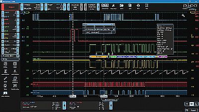
Also of note is that the decoding of serial protocols is included in PicoScope as standard. The decoded data can be displayed in graphs or tables or in both of these ways simultaneously. Serial protocols have become particularly important in vehicles because the growing number of vehicle convenience and comfort features have led to the demand for lower-cost wiring alternatives.
LIN (Local Interconnect Network) was developed to provide a common sensor/actuator bus standard. Initially introduced in 2000 as an inexpensive serial communication bus, the latest version (2.2A) is now standardized as ISO 17987. LIN uses a simple and low-cost single wire physical layer implementation based on ISO 9141 (as used by the K-line onboard diagnostic standard). This single-wire implementation does make LIN more susceptible to EMC than two-wire buses, which in turn limits the data rate to 20 kb/sec and the recommended number of nodes to 16.
Although serial buses like LIN offer several advantages, they also present difficulties during troubleshooting and debugging because data transmits in packets or frames that must be decoded before the designer can make sense of the information flow. Manually decoding (or “bit counting”) streams of binary data is error prone and time-consuming.
PicoScope includes decoding and analysis of widely used serial standards to help engineers see what is happening in their design to identify programming and timing errors and check for other signal integrity issues. Timing analysis tools help to show performance of each design element, enabling the engineer to identify those parts of the design that need to be improved to optimize overall system performance. Frames can be zoomed and correlated with acquired analog channels to investigate timing errors or other signal integrity issues that are root cause of data errors.
Serial protocols that PicoScope can decode include 1-Wire, ARINC 429, BroadR-Reach (100BASE-T1), CAN, DALI, DCC, DMX512, Ethernet 10Base-T and 100Base-TX, FlexRay, I²C, I²S, I3C, LIN, Manchester, MIL-STD-1553, PS/2, SENT, SPI, UART (RS-232/RS-422/RS-485), and USB protocol data as standard, with more protocols in development, and available in the future with free-of-charge software upgrades.
Data can be displayed in Hex, Binary, ASCII or Decimal formats. To help make decoded data even easier to read PicoScope enables use of a link file so that, for example, address hex 03DF can be displayed as “Oil Temperature,” or whatever the parameter means. A filter function displays only those packets that match user-defined condition(s). Statistics displays detail timing and voltage information on each packet, which helps to determine safe margins, noise immunity, and design reliability over extended operating periods.
Real-time PC-based scope features:
PicoScope 2000 Series: Smallest form factor enclosure that fits easily in a laptop bag and can be taken anywhere. USB powered and with bandwidths from 10 to 100 MHz, two channels or 2+16 channels MSO models. Ideal for education or for making waveform measurements on the move.
PicoScope 3000 Series: General purpose scopes to 200MHz with 2 or 4 channels plus 16 digital channels MSO models. A workhorse in the lab and perfect for home working.
PicoScope 4000 Series: High-precision scopes with fixed 12- and 16-bit resolution available. > 70dB+ dynamic range and differential input models available for making precision measurements from a few mV to hundreds of volts on non-ground referenced systems.
PicoScope 5000 Series: Versatile FlexRes scopes that can be set to make high speed timing measurements with 1ns resolution @ 8-bits vertical resolution or 12/14/15/16-bit vertical resolution at lower sampling rates. Suitable for laboratory or field use where there is a wide range of tasks to be performed day-by-day.
PicoScope 6000 Series: High-performance, deep memory scopes for demanding signal integrity and other scientific applications. Up to1GHz bandwidth and 4GS capture memory for performing big waveform data analysis.


Leave a Reply
You must be logged in to post a comment.