Capacitors and inductors can be combined to create resonant circuits, which have pronounced frequency characteristics. The amount of capacitance and inductance of these devices determine both the resonant frequency and the sharpness of the response curve (known as Q) that these circuits exhibit.
If the capacitance and inductance are in parallel, at resonance the parallel LC circuit acts like an open circuit with the circuit current being determined by any resistance in the circuit. So the total impedance of a parallel resonance circuit at resonance becomes just the value of the resistance.
There are many applications for resonant circuits, including selective tuning in radio transmitters and receivers and suppressing unwanted harmonics.
In a discussion of the LC oscillator, it is parallel resonance that is of interest. An inductor and capacitor in parallel configuration are known as a tank circuit. A condition of resonance occurs in the circuit when
XC = XL or 1/2πfC = 2πfL
Where f is frequency and C is capacitance and L is inductance.
Resonance happens when inductive and capacitive reactance are equal, which is to say 2πfL = 1/2πfC. This can happen only at a certain frequency. The equation can be simplified to:

From this information it is possible, knowing the capacitive and inductive parameters of a circuit, to find the resonant frequency. Alternatively, if a given resonant frequency is desired, L and C values can be chosen.
In a resonant circuit, Q denotes quality. Q is the peak (i.e. maximum) energy stored in a resonant circuit relative to the energy dissipated in the course of a cycle. It is the ratio of resonant frequency fr to bandwidth Bw. Because bandwidth is in the denominator, a circuit having higher Q will have less bandwidth: Q = fr/Bw
But it should be stated that in some applications, the Q of a resonant circuit is intentionally reduced. This can be done by introducing a “Q spoiling” resistor. In addition to being important in electronic circuits, Q is relevant in oscillating mechanical, acoustical, optical and other systems.
Generically speaking, an oscillator in an electronic circuit converts the dc supply voltage into an ac output, which can consist of a variety of waveforms, frequencies, amplitudes and duty cycles. Or the output can be a basic sine wave with no other harmonic content.
An LC oscillator, a subtype of the electronic oscillator, is often seen in radio-frequency applications because of its high-quality output and simple design. It consists of an amplifier incorporating positive (regenerative) feedback in conjunction with an LC resonant circuit with a proper Q parameter.
The objective when building an amplifier is to design a circuit that will not go into oscillation. In an amplifier not intended to operate as an oscillator, a limited amount of positive feedback can be used to boost the gain. A variable resistance can be placed in series with the feedback to prevent the circuit from going into oscillation. In an auditorium with a PA system, it is necessary to maintain separation between speaker and microphone to control feedback and prevent oscillation. The distance between the microphone and speaker behaves like a resistance for audio-frequency waves.
LC oscillators (unlike RC oscillators, which are non-resonant and based solely on a time constant) are tuned to ring at a specific frequency depending on the interaction of capacitive and inductive reactances. They are analogous to electromechanical resonators such as quartz crystal oscillators.
The process of measuring the resonance frequency of an oscillator circuit begins by coupling an RF signal generator to the circuit. The coupling between generator and oscillator must be loose. Otherwise, the output resistance of the generator may load the circuit and reduce its Q.
Next we set the generator to the frequency at which we want to measure the Q. We adjust the oscillator circuit (often by turning the tuner capacitor) to see maximum voltage in a scope probe connected to the tank circuit. The circuit is now in resonance, this frequency is the resonance frequency of the circuit.
We then measure the voltage of the oscillator circuit at resonance frequency. We vary the generator frequency a little above and below resonance and determine the two frequencies were the voltage over the circuit is 0.707 times the value at resonance. The voltage at 0.707 times resonance is the -3 dB point.
The oscillator bandwidth is the difference between the frequencies corresponding to these two 0.707 points. Then Q is the resonant frequency divided by this bandwidth.
The test setup typically includes a signal generator, a coupling coil, a scope and a 1:100 probe. The output of the signal generator connects to the coupling coil having about 50 turns. For frequencies in the megahertz range, we place the coupling coil about 20 cm from the oscillator circuit. The 20-cm distance is meant to give a loose coupling between the coil and oscillator.
 We then connect the probe to the oscillator circuit. The earth connection of the probe must connect to the housing of the tuner capacitor. The probe connects to the oscilloscope. The probe constitutes a small loading of the circuit, so the Q typically doesn’t drop much. There are also 1:1 and 1:10 probes, but these may load the oscillator circuit. A 1:100 probe typically has an input resistance of 100 MΩ and an input capacity of 4 pF.
Because of the 100x attenuation in the probe, the signal generator output generally must be set fairly high.
A sweep generator can simplify some aspects of this measurement. The “sweep output” connects to the X input of the oscilloscope with the oscilloscope in the X-Y mode. Now the scope trace runs from left to right with the left side being the start frequency and the right side the stop frequency. A good place to start is with the sweep frequency set at about 10 Hertz.
The Y input of the oscilloscope is connected to the oscillator via the 1:100 probe. The RF output of the sweep generator connects to the coupling coil, which is placed about 20 cm from the coil of the oscillator.
We can turn the tuner capacitor and get the curve of the oscillator on the oscilloscope screen. The amplitude knob of the sweep generator adjusts the height of the peak of the curve. The great advantage of this method is that changes in resonance frequency of the oscillator circuit can directly be seen on the screen. Also, changes in Q will be evident because the height of the peak will change.
LC oscillators come in the form of several subtypes:
 • The Armstrong oscillator, invented in 1912 by Edwin Armstrong, was the first electronic oscillator, as opposed to mechanical oscillators such as the pendulum which had been around forever. The Armstrong oscillator was originally used in vacuum tube transmitters. They later served in the regenerative receiver where the RF signal from the antenna coupled into the LC inductance by means of an auxiliary coil. The coil could be adjusted to keep the circuit from oscillating. This same circuitry functioned to demodulate the RF signal.
 • The Colpitts oscillator, invented by Edwin Colpitts in 1918, derives feedback from what may be considered to be a center-tapped capacitance. This is actually a voltage divider composed of two capacitors in series. The active device, an amplifier, may be a bipolar junction transistor, field effect transistor, operational amplifier or vacuum tube. The output connects back to the input through a tuned LC circuit constituting a bandpass filter that rings at the desired frequency.
A Colpitts oscillator can function as a variable frequency oscillator — as in a superheterodyne receiver or spectrum analyzer — when the inductor is made variable. This is instead of tuning one of the capacitors or by introducing a separate variable capacitor in series with the inductor.
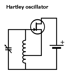
 • A Hartley oscillator, invented by Ralph Hartley in 1915, is a mirror image of the Colpitts oscillator. The difference is that rather than a center-tapped capacitance in conjunction with an inductor, it employs a center-tapped inductance in conjunction with a capacitor. The feedback signal comes from the center-tapped inductor or series connection between two inductors.
These inductances need not be mutually coupled, so they can consist of two separate series-connected coils rather than a single center-tapped device. In the variant having a center-tapped coil, the inductance is greater because the two segments are magnetically coupled.
In the Hartley oscillator, the frequency can be easily adjusted using a variable capacitor. The circuit is relatively simple, with a low component count. A highly frequency-stable oscillator can be built by substituting a quartz crystal resonator for the capacitor.
 • The Clapp oscillator, another LC device, similarly consists of a transistor or vacuum tube with a feedback network based on the interaction of inductance and capacitance set to the desired operating frequency. It was invented by James Clapp in 1948. It resembles the Colpitts circuit, with a third capacitor placed in series with the inductor. It is an improvement over the Colpitts oscillator, in which oscillation may not arise at certain frequencies making gaps in the spectrum.
 • The Peltz oscillator differs from the Colpitts, Clapp and Hartley oscillators in that it uses two transistors rather than a single amplifying device. Like other oscillators, the objective is to provide a combined gain greater than unity at the resonant frequency so as to sustain oscillation.
One transistor may be configured as a common base amplifier and the other as an emitter follower. The LC tank, with minimal impedance at the resonant frequency, presents a heavy load to the collector. The output of the emitter follower connected back to the input of the common base transistor maintains oscillation in the Peltz circuit.
To build an LC oscillator that is electrically tunable, a varactor (voltage variable capacitor) is placed in the LC circuit. The varactor is a reverse-biased diode. The capacitance of any PN junction, as in a diode, drops as the reverse bias rises. Specifically, the amount of reverse bias determines the thickness of the depletion zone within the semiconductor. The thickness of the depletion zone is proportional to the square root of the voltage that reverse biases the diode and the capacitance is inversely proportional to that thickness, and so it is inversely proportional to the square root of the applied voltage.
Accordingly, the output of a simple dc power supply can be switched through a range of resistors or a variable resistance to tune the oscillator. Varactors are designed to efficiently exploit this property.
A solid with any degree of elasticity will vibrate to some extent when mechanical energy is applied. An example is a gong struck by a mallet. If it can be made to ring continuously, it may function as a resonant circuit in an electronic oscillator.
Quartz crystal is imminently suitable for this role because it is highly stable with regard to its resonant frequency. Resonant frequency depends on the crystal size and shape. With accuracy up to one second in 30 years, quartz oscillators replaced pendulums in clocks and were unsurpassed in accuracy for years, until the 1950s, when atomic clocks entered the picture.
Quartz crystal as a resonator has the amazing virtue of inverse electricity. What this means is that when properly cut, ground, mounted and equipped with terminals, it will react to an applied voltage by changing shape slightly. When the voltage is removed, it will return to its original spatial configuration, generating a voltage that can be measured at the terminals. This vibration constitutes its resonant frequency.
Quartz crystal has another virtue, which is that it is inexpensive, so it is widely used in many applications including the world’s best oscilloscopes, spectrum analyzers, and arbitrary frequency generators.


hey! how can i find the inductor value if i have the center frequency? what is the formula?
Hey, it tells you at the start of this article/tution. Just transpose that equation.
My machine doesn’t have the symbols for pi or square root, and I couldn’t cut and paste the formula either.