Now that you know a little theory of near-field measurements, how do you use near-field probes and a spectrum analyzer to help you troubleshoot and mitigate emissions issues?
Remember, as mentioned in Part 1, that deciding whether to use an H-field or E-field probe depends on whether you’ll be probing high switching currents — di/dt for circuit traces, cables, etc. or high switching voltages, or dV/dt for switching power supplies, heat sinks, etc. respectively. Both are useful for locating leaky seams or gaps in shielded enclosures.
Typically, I’ll grab the medium or large-size H-field probe to start my survey because it’s mainly harmonic energy sources on PC boards that couple to wires and cables that in turn, serve as a radiating structure.

When selecting a probe set, you’ll see many manufacturers that sell near-field probe kits. Having used the set in Figure 1 for some twenty years, I can recommend the set from Beehive Electronics. The Beehive probe set is $325. You’ll also want to include the 1 m long SMB to SMA (or to N) cable for $50 or $75, respectively. They may be ordered directly from the Beehive Electronics website. Included are three different-sized H-field probes and an E-field probe. All three H-field probes include balanced E-field shielding and are epoxy-insulated for safe usage within live circuitry.
While the SMB connector is not as common compared to the usual N, BNC, or SMA connectors, it is ideal for near-field probes. The connector is a “push-on, pull-off” type, so connecting the probe is quick and easy. This also lets the probe rotate in relation to the cable, so you can change the orientation of the probe tip as you evaluate a PC board or cable.

H-field probes are most sensitive (will couple the most magnetic flux) when their plane is oriented in parallel with the trace or cable. It’s also best to position the probe at 90° to the plane of the PC board (Figure 2). E-field probes are similar in that they should be held at 90° to the component or structure being measured to couple the most flux lines into the stub.
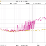
To set up the spectrum analyzer, I usually set the Start Frequency as 30 MHz and Stop Frequency as 1000 MHz, with a Resolution Bandwidth (RBW) according to most EMC standards of 120 kHz. Some spectrum analyzers won’t allow 120 kHz, so 100 kHz is close enough for general troubleshooting. Then adjust the Reference Level and Attenuation for an adequately detailed view of the harmonic response. This will give me the “big picture” of the harmonics. I may then lower the Stop Frequency to 300 or 500 MHz during the actual troubleshooting and energy source characterization.
I generally start with the larger H-field probe (Figure 3) and sniff around the product enclosure seams, circuit board(s), and attached cables to get a general idea of the various energy sources in the system and what structures may be coupling energy from on-board noise sources. The objective is to identify major noise sources and specific narrow-band and broadband frequencies.

Be aware that all seemingly high-harmonic energy sources you measure do not necessarily cause radiated emissions. It’s only when these high energy sources couple to wires or cables that you have the potential for emissions.
Document the locations and dominant frequencies observed. As you zero in on sources, you may wish to switch to the middle-sized H-field probe that I prefer. The smaller loop sizes will offer greater resolution (but less sensitivity). The smallest H-field probe may require either the built-in broadband preamplifier in the spectrum analyzer or an external one to boost the signal.
When applying potential fixes at the board level, be sure to tape down the near-field probe to reduce the changes in the probe tip’s location. Remember, we’re mainly interested in relative changes in harmonic amplitudes as we apply fixes.
Summary
While near-field probes are useful for identifying the various energy sources on boards, cables, or systems, they are only one component of a comprehensive troubleshooting philosophy, which will include RF current probes for measuring cable currents and close-spaced antennas to troubleshoot actual system emissions. The best part? All this may be done right on your own workbench, rather than at the EMC compliance test lab!
We’ll discuss how to interpret the harmonic emissions measured in Part 3 of this series (available September 21). Later articles will describe additional tools useful for troubleshooting radiated emissions issues.
References
Wyatt, Kenneth, Create Your Own EMC Troubleshooting Kit (Volume 1, 2nd Edition), Amazon, 2022
Wyatt, Kenneth, Workbench Troubleshooting EMC Emissions (Volume 2), Amazon, 2021


Leave a Reply
You must be logged in to post a comment.