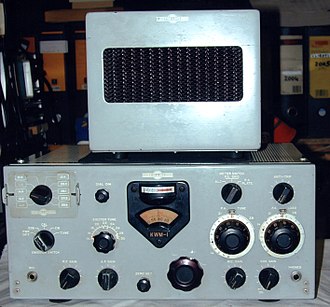
The most basic form of amplitude modulation is known as double-sideband AM, so called because mirror-image sidebands are produced above and below the carrier frequency. Early researchers found that they could use simple band-pass filters to eliminate one of the sidebands and even the carrier signal, improving the ratio of information-bearing power to total transmitted power, improving bandwidth utilization and reducing the amount of power consumed by repeaters. These techniques became known as single-sideband modulation (SSB) or single-sideband suppressed-carrier (SSB-SC) modulation.
In AM modulation, the entire signal is encoded in each sideband. A SSB receiver can process either sideband without the carrier, extracting the original baseband signal as it exists in the transmitter prior to modulation.

In an SSB transmitter, only one of the side bands is fed to the final amplifier. The reduced power consumption and bandwidth have enabled SSB to play an important role in the current overall transmission picture. It is not, however, used in modern broadcasting due to the expense and complexity of SSB at the receiver end, but it remains ubiquitous in point-to-point communication where the use of more complicated and expensive transmission equipment can be justified.
SSB was patented in 1915 and in the post-World War II electronics explosion, amateur radio operators used SSB extensively and by the mid 1950s it dominated aircraft communication. An SSB signal can be produced by filtering out the carrier and one of the sidebands. The preferred method is to eliminate the lower sideband. SSB works because in ordinary AM, the two original sidebands are symmetrical, so no information is lost by demodulating only one. An advantage in SSB, other than bandwidth conservation, is SSB’s greater power after final RF amplification. This is because in conventional AM, transmission of the carrier and one of the sidebands requires over half the transmitter’s power. The only downside is that SSB cannot be demodulated by means of a simple envelope detector. This adds to the cost of every receiver, which is why SSB is not used in standard AM broadcasting.
The Hartley modulator eliminates the unwanted sideband using a technique known as phasing. It works by generating two versions of the original signal 90° out-of-phase with respect to one another for each frequency component. Each of these signals modulates two carriers that are also 90° out-of-phase with respect to one another. When these signals are then added or subtracted, a lower or higher sideband remains.
Some home-brew experimenters have seen as a disadvantage in the Hartley modulator the fact that shifting the baseband signal 90° out-of-phase cannot be done simply by delaying it, because the baseband signal contains a range of frequencies that would be shifted different amounts. A wideband 90° phase-difference network is required. This circuitry uses the Hilbert transform to phase shift the baseband audio, and it can be done inexpensively.
Mathematically, a Hilbert transform applies a convolution with the function 1/(πt) to the original signal. The convolution is the integral of the product of the two functions after one is reversed and shifted. The integral is evaluated for all values of shift, producing the convolution function.
Another SSB modulator is known as the Weaver modulator. Widely used in digital implementations, it is comprised solely of low-pass filters and quadrature mixers. The sideband to be used is first centered at zero, using quadrature sine and cosine modulators at that frequency. This complex signal then passes through a low-pass filter, removing the superfluous sideband. Finally, the SSB complex signal is transformed into a real signal by another pair of quadrature mixers to the desired center frequency. This all takes place within the transmitter.
Similarly, SSB receivers differ from ordinary AM receivers. The typical demodulator in an AM receiver is an envelop detector. In contrast, SSB receivers use product detectors. Rather than converting the envelope of the signal into the decoded waveform like an envelope detector, the product detector puts the modulated signal and a local oscillator through a mixer to form the product of the two, hence the name. Thus a product detector is also a frequency mixer. An it produces an audio-frequency copy of the original audio signal and a mixer product at twice the original RF or IF frequency. This high-frequency component can then be filtered out, leaving the original audio-frequency signal.
 If you examine the modulated RF signal, you’ll see an envelope of the signal–basically the extremes of the modulated signal–that is related to the audio or baseband signal being modulated on to the RF signal itself. The largest excursion the largest magnitude of that envelope is called the peak of the envelope. This factor is important because the power measurement for an SSB signal is often defined by its peak envelope power.
Discussions of RF power often concern the RMS voltages which can be computed by looking at the peak voltage divided by square root of two. In most RF applications the voltage is measured into a 50-Ω impedance. So power into a 50-Ω load is simply computed by squaring the RMS voltage and dividing it by 50 Ω, i.e. P=Vrms2/50. So for a peak envelope power calculation, we look at the peak excursion of the envelope voltage at a specific time, and then compute power from P=Vrms2/50 at the of the excursion of the RF signal. In the case of the SSD RF envelope
It is illuminating to review a few RF AM envelopes. With ordinary AM without any audio input, the envelope of the AM carrier is not zero. It is half of the maximum peak-to-peak voltage. This is to prevent envelope minimums at 100% modulation from reaching zero volts, a condition that would create audio distortion. Thus the ideal AM carrier magnitude is half the voltage that occurs at maximum peak excursion, which means it’s one-quarter the power that occurs at the max peak envelope power. For example, a 100-W AM transmitter the ideal carrier amplitude would be 25 W. In contrast, the SSB has no output when there is no audio input and, thus, no envelope.
If a single tone is applied to an AM transmitter the result is an RF envelope where the upper and lower envelopes are essentially inverses of each other that follow the amplitude of the baseband or audio signal. In the case of SSB, a single audio frequency will result in a constant-amplitude, constant-frequency RF envelope. Consequently, application of a single tone to an SSB transmitter provides a way to measure peak envelope power directly with an RF power meter.
However, sometimes commercial SSB transmitters are not rated to put put out full peak envelope power continuously as would happen in the transmission of a single tone. So often a two-tone measurement is used for power measurement. The usual approach is to adjust two audio tones so they each create the same amount of RF excursion. One interesting property of the two-tone SSB modulated signal is that a power measurement with a conventional average-responding wattmeter will yield a reading equal to half of the peak envelope power. This behavior provides an easy way of measuring the peak-to-peak envelope power of an SSB transmitter without going to full 100% duty cycle.
In contrast, a two-tone signal applied to an AM transmitter creates an RF envelope that is the the sum of the two tones. Its shape will vary depending on the frequency of the two tones. Though two-tone modulation in ordinary AM is generally not used for measuring power, it is often used to gage modulator linearity. The usual approach is to examine the demodulated two-tone signal on a spectrum analyzer and look for third-order products generated by nonlinearities in the transmitter.


Leave a Reply
You must be logged in to post a comment.