Simply stated, a magnetic field is analogous to electrical voltage, while magnetic flux is analogous to electrical current. A magnetic circuit is analogous to an electrical circuit with important differences. Electromotive force in an electrical circuit corresponds to magnetomotive force. Resistance and its reciprocal, conductance, in an electrical circuit corresponds to reluctance and its reciprocal, permeance, in a magnet circuit. But there are subtle ways in which the forces correspond only roughly, and comparisons are imperfect.
Another way to put it is that magnetic field strength (H in amperes per meter) is the amount of magnetizing force. This force is directly proportional to current carried by a conductor and the length of the conductor. Magnetic flux density (B in tesla or Weber/m2) is the amount of magnetic force induced on the given body due to the magnetizing force H. The amount of magnetic force induced depends upon the strength of H and the nature of the medium.
A magnetized body has a north and south pole, and these poles always exist in associated pairs. If you cut a bar magnet in half to make two shorter bar magnets, each of the new magnets has north and south poles. A magnetic monopole has never been discovered.

The magnetic field associated with a permanent magnet can be demonstrated by placing a sheet of paper over the magnet and randomly sprinkling iron filings on the paper. Each particle quickly becomes magnetized with its own north and south poles, and because their opposite poles attract, they form lines representing the magnetic field. The density of the lines (number of lines per millimeter) and direction of the lines illustrate that the magnetic field is a vector field. The lines change direction and become closer together or farther apart as the field density changes.
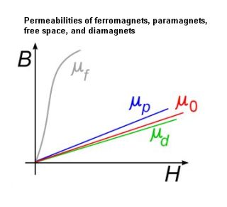
Iron filings can show the direction and intensity of the magnetic field, but they are not the vector field itself. They are like footprints on sand or ripples in a moving stream, not the actual water. B and H are proportional in a vacuum, but they diverge inside magnetic materials. Magnetization, denoted by upper-case M, is a measure of the degree to which materials respond to an applied B field. Diamagnetic materials produce a magnetization that opposes the applied field. Paramagnetic materials produce a magnetization in the same direction as the applied field.
In both instances, M is usually proportional to the applied magnetic field. The relation between B and H is B = μH, where μ is permeability of the medium through which the flux passes. Permeability varies for different materials and is often hysteretic, meaning it demonstrates hysteresis in its reaction to magnetic fields. Iron is highly permeable to a magnetic flux.
Magnetic flux is quantified first by establishing an imaginary surface. This surface is strictly a mathematical construction and may coincide with or intersect the surface of the magnet. Magnetic flux is a measurement of the amount of flux flowing through the surface. Specifically, it is the larger number of lines flowing in one direction through the surface minus the small number of lines flowing through the surface in the opposite direction, or zero if they are equal.
The relevant equation for magnetic flux density, Φ, is Φ = BA cosθ. A represents the area of the surface. Where the surface is perpendicular to the magnetic field, cosθ = 1. Where the surface is at an angle to the lines of force, cosθ is less than one. The SI unit of magnetic flux is the Weber. Flux density is magnetic flux divided (vectorially if it is at an angle) by the area of the surface in tesla units.
Electrical current in human-made wiring flows through insulated conductors. In the magnetic domain, there are no absolute insulators, but instead all materials have more reluctance or less reluctance, i.e. less or greater magnetic permeance. That is why in the iron filings experiment, the lines representing the magnetic field extend well beyond the actual magnet. In motors, transformers and similar devices, magnetic flux is channeled through iron cores, to do the work that is desired.
Magnetic flux, driven through the magnetic circuit by applied magnetomotive force, is expressed by F = ϕR where F is the magnetomotive force across all or part of a magnetic circuit, ϕ is the magnetic flux through a given segment, and R is the magnetic reluctance of the segment.
The defining difference between an electrical circuit and a magnetomotive circuit is that power dissipation is associated with resistance but not with reluctance. An electrical field causes current to follow the path of least resistance, and a magnetic field causes magnetic flux to follow the path of least reluctance.
Maxwell’s equations state that magnetic flux always forms a closed loop. Magnetic circuits are nonlinear. Reluctance varies, depending upon the magnetic field. When the magnetic flux rises above a specific level, the permeable material saturates, so there can be no further rise in the amount of flux, which is limited by runaway reluctance. No such phenomenon occurs in a resistive electrical circuit.

The typical way of measuring magnetic fields is with a magnetometer. Vector magnetometers measure the vector components of a magnetic field, whereas total field magnetometers or scalar magnetometers measure just the magnitude of the vector magnetic field.
There are several technologies used for magnetometers. The ordinary compass is, in fact, a simple magnetometer. It’s needle measures the direction of the field. The oscillation frequency of a magnetized needle is proportional to the square-root of the strength of the ambient magnetic field.
One of the most straightforward magnetometer technologies is the inductive pickup coil which measures magnetization by detecting the current induced in a coil caused by the changing magnetic moment of a sample. The sample’s magnetization can be changed by applying a small ac magnetic field (or a rapidly changing dc field), as in capacitor-driven pulsed magnets. These measurements require differentiating between the magnetic field produced by the sample and that from the external applied field, often through use of cancellation coils. Typically, half the pickup coil is wound in one direction, the other half in the other. The sample sits in only one half. The external uniform magnetic field is detected by both halves of the coil. Because they are counter-wound, the external magnetic field produces no net signal.
There are numerous more exotic magnetometer technologies. Vibrating-sample magnetometers (VSMs) detect the magnetization of a sample by mechanically vibrating the sample inside an inductive pickup coil or SQUID coil. Induced current or changing flux in the coil is measured. Pulsed-field extraction magnetometry also makes use of pickup coils to measure magnetization. Here, the sample is secured and the external magnetic field is changed rapidly. One of several techniques must then be used to cancel out the external field from what the sample produces. These include counterwound coils that cancel the external uniform field and background measurements with the sample removed from the coil.

Magnetic flux is usually measured with a fluxmeter, which contains measuring coils and electronics that evaluate the change of voltage in the measuring coils to calculate the measurement of magnetic flux.
Fluxmeters are basically integrators, used because of the physical relationship between coils of wire and magnetic flux. The instantaneous voltage produced across a coil is proportional to the number of turns in the coil times the rate-of-change in flux. It is problematic to use this rate-of-change relationship directly for dc measurements because the voltage disappears as soon as the flux stops changing. The voltage is also proportional to the rate-of-change in flux and not to the total change in flux which is usually the parameter of interest.
If the voltage across the coil is integrated to look at the area under it plotted against time, the above problems disappear. The integrator output is proportional to the total change in flux and rate-of-change does not matter.


Hi sir
I have doubts in Transfomer open circuit testing
I applied 3 phase 420 v in primary side of the Transfomer while secondary of the Transfomer was open condition then primary winding taking some mill Amps current
How can I say this mill Amps current is correct value when I am doing open circuit testing of the Transfomer
Hi Saravanan,
I will endeavor or to answer your question, but I need some more information.
1. What is the exact amount of current that you measured?
2. Was that current across the primary, or was it primary to ground?
3. What is the make and model of the transformer?
David