A new version of the USB spec puts additional demands on testing regimes that wring out power-handling options.
David Maliniak | Teledyne LeCroy
Since its official debut in 1996, the Universal Serial Bus (USB) protocol has seen numerous revisions spanning three generations of the standard, with USB 4.0 waiting in the wings for later in 2019. Meanwhile, in parallel, the USB Implementer’s Forum (USB-IF), which oversees the USB standard, has maintained parallel development tracks for USB interconnects and USB Power Delivery (USB PD) technology.
The USB Type-C interconnect (2014) brought a smaller, slimmer plug that’s reversible, eliminating the fumbling around to properly align the plug with the jack. USB Type-C also delivered higher data transfer rates and higher charging voltages/currents. When USB 3.1 arrived, so did USB PD 2.0. Now, USB 3.2 has been released as has PD 3.0. It is useful to review some of the changes from PD 2.0 to the current 3.0 revision of the standard as well as elements of PD compliance testing.
USB PD is a specification for handling higher power on USB and allows a range of devices to charge quickly over a USB connection. It facilitates negotiation between two devices for a power contract, so they can determine how much power can be pulled from the charger. Power Delivery starts at the 5-V setting and is configurable up to 20 V. Using a standard USB-C cable, it can handle up to 60 W and will go up to 100 W using a full-featured USB Type-C (ECMA) cable.
Another point of interest regarding Power Delivery is that it allows for power to flow both ways, with no set direction based on circuit or connection. For example, if you were to connect two phones that support Power Delivery with a USB-C charging cable, one phone could charge the other and vice versa.
A newly introduced PPS (Programmable Power Supply) protocol requires that a PPS-capable sink be able to request adjustments of source output voltage in increments as small as 20 mV. Likewise, the sink can request source current limits in 50-mA steps. The sink should check in with the source at least every 10 seconds with a voltage/current request. Sources operate in constant-voltage or current-limit modes depending on the load; current-limit mode happens only when the sink attempts to draw more than the negotiated current.
Power Delivery 3.0 vs 2.0
There are a number of significant differences between the PD 2.0 specification and the latest 3.0 specification:
Power Delivery Profiles (PDPs): Since the PD 1.0 specification, USB PD’s Power Profiles were a way to communicate power-supply capabilities to a USB end

user. PDPs are a revamp of Power Profiles that now tell the user what the power supply can deliver in Watts; a higher value means more power. A PDP is the highest nominal voltage times the nominal current reported in fixed Power Delivery Objects (PDOs).
Standards-Based Charging: For years, the USB Implementer’ Forum (USB-IF), which oversees the USB standard, has been working to globally standardize around USB for charging. The International Electro-Technical Commission (IEC) has long since formally adopted USB, and more recently, USB Type-C and PD.
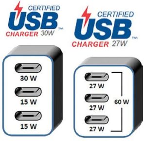
USB PD Multi-Port Chargers: PD 3.0 needed a way to communicate PDPs to multi-port chargers. The standard settled on two categories of charger ports—Assured-Capacity Ports and Shared-Capacity Ports. In the former case, each port is able to deliver its rated/labeled power capacity independent of all other ports. In the latter, each port is able to deliver its rated/labeled capacity depending on the remaining available capacity that’s shared among multiple ports. The total available power capacity of the multiple ports is indicated to the user, and all ports on the charger are capable of delivering the same power rating. So, for example, as long as one port on the charger can maintain 30 W, charger packaging can claim a PDP of 30 W.

PPS: Another outcome of the USB-IF’s efforts to create an international standard that uses the USB Type-C interconnect is the concept of PPSs. There are two usage models: Powering devices in use with a fixed source and charging of battery-powered devices. The fixed-voltage features were in place with PD 2.0; PD 3.0 introduces PPS, which attempts to make battery charging more efficient.
For power delivery to devices, the key characteristics include a fixed-voltage supply, stable current, and the ability to handle dynamic loads. For battery charging, the source must deliver variable voltage and current and account for charging rate and thermal constraints. Most battery manufacturers recommend beginning with a constant current and gradually increasing voltage followed by constant voltage and gradual reduction in current.

With fixed PDOs, the charger advertises its maximum output and the sink side chooses the closest fit. Fixed-voltage chargers are typically unable to charge quickly without generating excessive heat. In the PPS methodology, however, the sink “micro-manages” its own charging regime by requesting that the source make voltage changes in small steps. As a result, charging completes in less time while keeping heat under control, which can also help extend the battery’s lifespan. Once the source reaches predetermined voltage level, the sink re-negotiates by requesting a constant voltage.
New PD 3.0 terminology for PPS mode: Many different devices might be plugged into a given PD charger, but PD aspires to universality. Thus, the PPS approach demands that the sink side be smarter, given that the sink knows how much power it needs. This gives rise to the new term Augmented PDO (APDO) to define chargers that can deliver a range of voltages. Yet, a maximum current still must be defined. PPS sinks will now use what are termed Request Data Objects (RDOs) to make these real-time dynamic adjustments to power.

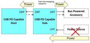
Fast Role Swap (FRS) Hub: This new PD 3.0 feature specifically targets USB hubs and docking stations. Typically, users plug their docks into a wall outlet; thus, it is the dock that is powering a laptop and any other USB-powered accessories plugged into the dock. If power is lost by, say, the cord being unplugged, users run the risk of losing data being saved to a USB device attached to the dock at that moment.
FRS hubs detect the loss of ac power and quickly perform a “power role swap.” Upon sensing loss of power, the dock speculatively signals FRS by pulling VCC to ground for 60-120 µsec. The dock must have hold capacitors that can maintain Vbus at 5 V for at least 150 µsec after Vbus falls below 5 V. In this manner, the unpowered dock continues to source Vbus on its downstream ports while the Fast Role Swap takes place.
After a power loss, the sink must be monitoring VCC. When VCC goes low for 30-60 µsec, that constitutes a Fast Role Swap request, and the sink then becomes the source by supplying 5 V to the bus. The key here is that this FRS capability is relevant only for Dual-Role Power (DRP) ports that can alternate between sink and source roles.
Extended Messages: PD 3.0 offers an extended payload size for larger data transfers with packets of up to 260 bytes. Initially, these larger packets were added to allow firmware updates delivered over the PD channel, but their usage was extended into arenas such as security (authentication), battery information, and other data.


the way they describe the test procedure is very proficient I checked also I got good results and I recommend all of you to prefer first this it is a very good technique.
is there a fallback standard for PD charger to non PD phone
or QC Charger to PD phone and so on
it would be useful to know what will happen if all i need is a 5v 1amp charge for my whatever will a PD C charger do that with a USB C to USB A adapter