A fuel cell converts oxygen or another oxidizing agent and hydrogen or some other fuel into electricity and heat. A third byproduct, depending on the fuel used, is methane or another non-earth-friendly substance. But the most basic fuel cell combines hydrogen and oxygen to produce pure water. This simple, long-lasting device with no moving parts has the potential to play a role in mitigating our climate-change problems.
“Wait a minute,” you might say. “If heat is a byproduct, won’t it contribute to, rather than mitigate, global warming?” Not really. (Though at least for now, the process for making hydrogen is energy intensive and not particularly green.) To see why, we must examine the heat cycle and the role of hydrogen fuel cell.
There are types of fuel cells that consume fuels other than hydrogen, including hydrocarbons. Some produce prodigious amounts of carbon dioxide and worse, forming a dense translucent barrier blocking solar radiation and promoting an avalanche of irreversible temperature rise. The hydrogen-based fuel cell, in contrast, produces only electricity, water and a small amount of heat, which can be used year-round and even be converted for interior cooling.
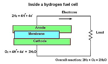 All hydrogen-based fuel cells consist of three essential parts: anode, cathode and electrolyte. The conversion process is electrochemical, and there is no combustion. One chemical reaction takes place at the anode and a second at the cathode. At the anode, which may be considered the input, a catalyst enables the fuel to participate in an oxidation process that produces free electrons and positive ions which are hydrogen nuclei. A single electron is stripped from the atom and, because there is no neutron, all that remains is the proton, which is the same as a positive hydrogen ion.
We normally think of an anode as positive and a cathode as negative, but in a fuel cell that is not, strictly speaking, the case. How can the positive hydrogen ions and the negative electrons both flow, albeit by different routes, from anode to cathode?
The positive ions move toward the cathode. That is because oxygen gas, removed from the surrounding atmosphere, is forced through a platinum catalyst where it forms negative-charged oxygen atoms. The negative charge attracts two positive hydrogen ions, combining with an oxygen atom to form a water molecule, H2O. Thus, there are two interdependent simultaneous electrochemical reactions, oxidation at the anode and reduction at the cathode. The byproducts are usable electricity, water, and a small amount of heat, much less than would result from combustion of an equal amount of hydrogen or other fuel. If the heat is captured and used to generate electricity, the fuel cell contributes no net heat to the atmosphere.
The two electrochemical reactions collectively are known as a redox (reduction-oxidation) reaction. Oxidation and reduction in a fuel cell happen simultaneously, although at different locations, and they do not happen independently. Although oxidation usually involves the formation of oxides from oxygen molecules, this is not always the case. Currently, the word oxidation is used to describe other reactions involving loss of electrons in which oxygen does not necessarily play a role.
Multiple types of fuel cells exist. They are named according to the kind of fuel oxidized at the anode. The principal variations are:
Solid Oxide Fuel Cells (SOFCs) operate at a higher temperature than other types, typically at 1,800°F, necessary to permit conduction of oxygen in the electrolyte. These devices use a non-platinum catalyst and natural gas fuel which permits electrical efficiencies in the 50-60% range and 70-80% in combined heat and power (CHP) devices. SOFCs are suitable for large commercial and small residential installations.
Proton Exchange Membrane Fuel Cells (PEMFCs), another name for hydrogen fuel cells, have a platinum catalyst that lets them operate at a lower temperature, 80-200°F, permitting use of hydrogen fuel. At 40-60% efficiency, large output power variations are tolerated where quick acceleration is required, as in vehicles. These fuel cells have also been widely used as stationary units for backup power in telecommunications installations.
Molten Carbonate Fuel Cells (MCFCs) incorporate a ceramic matrix electrolyte. A 1,200-°F operating temperature and a non-platinum catalyst keeps down costs. The natural gas fuel is converted internally to hydrogen, enabling stationary applications.
Phosphoric Acid Fuel Cells (PAFCs) with a ceramic electrolyte and platinum catalyst tolerate fuel impurities, suggesting use in schools and hospitals.
Alkaline Fuel Cells (AFCs) have worked in underwater and aerospace missions that need drinking water where cost is not the decisive factor. A 60-90% efficiency has been attained.
Direct Methanol Fuel Cells (DMFCs) with a polymer membrane electrolyte derive hydrogen from liquid methanol operating at a temperature of 125-250°F. They are used in laptops and consumer device battery chargers and also for stationary power.
Each fuel cell produces a small electrical potential, typically 0.7 V. But like solar cells in a photovoltaic array, multiple units can be wired in series for a greater voltage output or in parallel for higher current. Additionally, boosting cell surface area increases current output.
An essential part of the fuel cell is the catalyst, which facilitates the oxidation reaction at the anode. Catalysts increase the rate of chemical reactions. They are not consumed but instead act repeatedly so they need not be replenished. In a fuel cell, various metal-containing catalysts enhance the two complementary reactions. In one type of fuel cell catalysis, platinum nanoparticles join to larger carbon particles, increasing the rate of oxidation. The reaction initiates and proceeds at a lower temperature.
Measurements of fuel cell operation begin with an equation that expresses theoretical cell voltage: E =∆gf/F where E= cell voltage; ∆gf= the energy required to move a charge Q through a potential E if the quantity of charge oxidized at the anode and reduced at the cathode for one mole of reactant are matched; and F= Avogadro’s number. In practice the cell always generates energy below this value. The amount of the difference indicates the health of the cell.
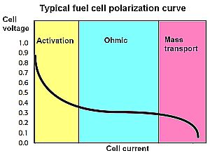 The most common electrical test of a cell is what’s called the polarization curve, simply the steady-state cell current vs. voltage. There are three regions of operation that arise because of different kinds of internal cell losses. In the activation region, the cell voltage drops quickly under even a small load current. This fall-off begins when the load current exceeds the normal forward/reverse reaction rate (exchange current) at the cathode. After the initial drop, the cell voltage continues to fall because of resistive losses in the ohmic region. In response to rising load current in this region, the forward reaction at each electrode climbs relative to the reverse reaction. It is the energy required to accomplish this change that is indirectly responsible for the drop in cell voltage. An increasing load at some point becomes excessive, demanding more fuel than the anode and cathode can support. This is generally called mass transport loss.
 The three types of losses (activation, ohmic, and mass transport) are present throughout the entire operating curve. The ohmic losses appear small at low currents compared to the activation losses in the first part of the curve. Similarly, activation losses appear small compared to the ohmic losses when the cell currents are large (in the ohmic region). As these losses reduce cell voltage, so too does cell efficiency. A rough approximation is that cell efficiency is equal to cell voltage expressed as a percentage–i.e. a cell voltage of 0.7 V represents a cell operating at about 70% efficiency.
A measurement more important than cell efficiency is over-potential. All chemical reactions need some small activation energy. More reactions per unit time (a higher load current impressed upon the cell) demand rising amounts of activation energy because of the larger number of reactions. The result is a greater activation voltage drop, called over-potential. Over potential affects the reliability and lifetime of a cell.
Life and reliability problems get worse when the cell operates in the mass transport region. Here, only ions are capable of traveling through the electrolyte membrane. So a spurious REDOX reaction provides some of the load current. The cell voltage can drop precipitously. Load current maintained at such an elevated level can cause the electrode surfaces to deteriorate.
In electrochemistry studies it is common practice to fix the cell potential (potentiostatic control) and measure the resulting cell current. But fuel cell measurements typically force a cell current (galvanostatic control) and measure the resulting voltage.
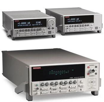
There are several reasons for this practice. One is that a good cell with low membrane ionic resistance will have a flattened ohmic region. If potentiostatic control is used, even small variations in the voltage can cause large changes in load current. Also, fuel cells are low impedance devices (large ones especially have internal resistance in the milliohm to microohm range) and can be measured with lower noise by sourcing current and measuring voltage rather than vice versa. Because potentiostatic control fixes the cell potential with respect to the voltage measuring terminals, noise in the voltage driving the cell generates significant noise current through the cell’s low impedance. By contrast, under galvanostatic control, a relatively large current is forced through the cell. The current is measured as a voltage across the test instrument’s internal current-sensing resistor. This resistance is decades larger in value than a cell’s internal resistance, so noise in the measurement is a much smaller percentage of the signal.
It turns out that fuel cells have an internal impedance rather than a strictly resistive behavior. The reason is they have a capacitance that arises from chemical reactions at the electrolyte membrane (referred to as double-layer capacitance), and an internal inductance. The real component of the cell impedance, referred to as the internal resistance or membrane resistance, is relatively low. But it is a critical factor in the performance of the cell. It is responsible for the real component of the energy lost by operating the cell under load. Consequently, it’s accurate measurement is important.
Measurements of internal resistance usually involve measuring the cell voltage at a specific load current, then briefly open-circuiting the load and measuring cell voltage during the interruption. Though this sounds simple, the procedure isn’t trivial. The magnitude of the cell impedance changes with frequency because of the internal reactive components. The frequency of the measurement must be high enough (i.e., current interruption short enough) to eliminate the effects of the total cell reactance.
The trick to setting up the measurement is to do so in a way that the impedance associated with cell inductance exactly cancels the impedance of the double layer capacitance, leaving only the internal resistance in the measurement results. This involves keeping the interruption brief. Also, it is common practice to only partially interrupt the load current so the cell disturbance is only a small percentage of the polarization current. The point is to keep the cell chemistry and the cell’s small signal model unaffected by the disturbance. This partial interruption may make it possible to use a longer interrupt time, typically between 20 and 200 μsec.
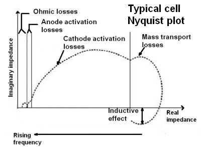 Nyquist or Cole-Cole plots are frequently used to describe the internal operation of a cell. They combine the resistance, inductance, and capacitance lumped elements of the cell into a single complex number consisting of a magnitude and phase angle, or equivalently, as real and imaginary components of impedance at each frequency. As is usual with complex numbers, the real part of the impedance is plotted on the x-axis and the imaginary component on the y-axis. The portion of a Nyquist plot that crosses the x-axis represents the real resistance as measured by the interrupt measurement.
Nyquist analysis provides useful information on the reactions within the fuel cell. Electrical testing of the cell current essentially measures the cell reaction rates by counting electrons as they move through the external circuit, exactly two for every reaction. In a Nyquist analysis, useful electrochemical information is usually in the 50 kHz to 0.01 Hz range. The wide frequency range arises because different reactions within the cell have different time constants. For example, the charge-transfer resistance and the electrode capacitance delay the voltage change on the double-layer capacitance of the cell when a step load current is applied. Thus, a Nyquist representation can separate the charge transfer resistances and their reaction time constants for the REDOX reactions taking place in the cell. The plot also isolates other activity such as parasitic corrosion reactions, membrane resistance, double-layer capacitance, and cell inductance: Each reaction is represented in the Nyquist plot as a separate “bump” or semicircle.




Leave a Reply
You must be logged in to post a comment.