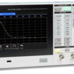
Most digital storage oscilloscopes include an internal arbitrary function generator (AFG). In the Tektronix MDO3000 instrument, there is a port on the back panel labeled AFG Out. To control the AFG and display its output, connect a BNC cable to this port and plug the other end into one of the analog channel inputs or into the RF input, using an RF adapter, on the front panel.

Alternately, the internal AFG output can be fed to a separate instrument or injected at various points on a circuit board. For this, a BNC breakout cable with alligator clips rather than the usual connector is suitable, used in conjunction with multimeter probes.
The word “arbitrary” in the context of a function generator means the function generator can create, edit, display and store custom waveforms produced by the user.
Also, the AFG contains an internal library of 13 waveforms. With the BNC cable connected to one of the analog channel inputs, that channel turned on and AFG activated, press the soft key associated with waveforms to see a list of the internal waveforms. Sine is the default. Using Multipurpose Knob a, the user can scroll down through the list of waveforms, displaying each in turn. They are: Sine, Square, Pulse, Ramp, dc, Noise, Sin(x)/x, Gaussian, Lorentz, Exponential Rise, Exponential Decay, Haversine and Cardiac.
The oscilloscope display consists of the vertical range scale, which in the time domain measures out amplitude in volts. The horizontal domain scale measures out time in seconds. The range is a function of the domain, not the reverse. Amplitude is a function of time. Only in a strange universe would you say that time is a function of amplitude.
At any instant in time, the amplitude of a given signal is a dot somewhere on the screen. The dot moves at a uniform rate from left to right on the screen, and usually at a non-uniform rate vertically. A line drawn through the dots shows the changing voltage as time progresses.
The soft key associated with Waveform Settings brings up a vertical menu on the right side of the screen. For the waveform currently displayed, the user can adjust Frequency and its reciprocal, Period, and also Amplitude and Offset, using Multipurpose Knobs a and b. (Frequency is not applicable to Noise and DC.) As they are adjusted, the values in the horizontal AFG information bar at the bottom of the display change. If you disconnect the BNC cable from the analog channel input and measure the signal with a multimeter, you will see these values change. The values are not the same for all waveforms. For example, the upper-frequency limit for sine wave is 50.000 MHz, while for square wave it is only half as great, 25.000 MHz. That is because of the fast rise and fall times that characterize the square wave.
By pressing the soft key associated with Output Settings, the corresponding menu comes up on the right. The first menu selection is load impedance. The normal setting is High Z. This high impedance, the default, will not affect the circuit to which it connects. On rare occasions, you may want to change load impedance to 50 Ω, for impedance matching. However, large amounts of current may flow in the circuit, so use this low impedance setting only when necessary.
The second menu selection is interesting. It lets the user add varying amounts of noise to the AFG signals, ranging from 0 to 100%. Notice that at the default frequency, most signals lose triggering at about 30% added noise.
Added noise is useful in examining the effectiveness of noise abatement techniques. For example, a noisy signal can often be improved by employing bandwidth limiting. That is because noise is a broad-spectrum phenomenon. By limiting the bandwidth, you can remove a large amount of noise without affecting the signal. This depends, of course, upon the signal having a sufficiently low bandwidth so that it is not tuned out.
Another effective noise abatement technique is signal averaging (also called waveform averaging). It works only on periodic signals that are repetitive. The identical repeating signals are averaged to make a composite signal. The number of waveforms that are averaged can be set by the user in stages between two and 512. Because noise is not periodic and not repetitive, it is eliminated in this process, while the signal under investigation is retained. Signal averaging is accessed by pressing Acquire>Mode>Average.
The next Output Setting menu selection is Aux Out. This refers to the port next to AFG Out, on the back panel, which we are currently using. It can be set to output the main trigger, or event or act as a second AFG source.
Finally, the bottom Output Settings selection is User Preset. It sets the signal amplitude at logic levels used in four common logic types.
If we unplug the BNC cable from the analog input channel and swing it over to the RF port equipped with an RF adapter, it’s a whole new world. Now, any of the waveforms as synthesized by the AFG and conveyed to the front panel, are displayed in the pure frequency domain, as opposed to the former mixed-domain mode as we have seen when pressing Math>FFT.
After RF is toggled on and AFG pressed to reactivate it after enterring the RF mode, the default sine wave displays. It is difficult to discern because the fundamental exactly coincides with the left edge of the display, and there are no harmonics to raise prominent spikes above the noise floor. To see the sine wave in the frequency domain mode, in the RF section press Freq/Span. The vertical Frequency and Span menu to the right of the display permits the user to format the signal so as to obtain a meaningful screen.
In the RF information bar at the bottom, as well as in the Frequency and Span menu on the right, Center Frequency is shown as 1.50 GHz. And in the AFG information bar after pressing AFG once more, the actual sine wave frequency as exported from the internal AFG is shown to be 100.00 kHz. We have to make these two metrics coincide. This is best done by using the keypad to enter into the highlighted Span field 100 kHz. Instantly, the trace shifts, the fundamental flying to the center of the screen.
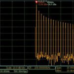
To make things interesting, once more press AFG>Waveform and using Multipurpose Knob a, scroll down to Pulse. Here the trace doesn’t look much different. Now you should see prominent harmonics generated by the fast rise and fall times.
The reason these harmonics do not appear in the display is that the Span, made visible by pressing Freq/Span in the RF section, 3.00 GHz, is almost 3,000 times too great. In this display, the harmonics are pressed against and obscured by the fundamental. To correct this situation, press the soft key associated with Span and using the keypad, enter 5 MHz. Notice that the harmonics instantly appear. Start and Stop are automatically revised without user intervention. You can press Menu Off to obtain a better view.
Now you can use Multipurpose Knob a to access any of the 13 waveforms provided by the AFG. The Center Frequency and Span settings are retained, so they do not have to be reset. If you power-cycle the oscilloscope and press AFG once more, the Center Frequency and Span settings return. If you press Default Setup, they are gone.
Besides the Frequency and Span menu in the RF section, there are three additional buttons that affect the appearance of the AFG signal displayed in the frequency domain. Directly below Freq/Span is Amplitude. The first menu selection is Reference Level, which can be adjusted by turning Multipurpose Knob a. This moves the trace down or up into the clipping area with possible distortion. This clipping area coincides with the upper limit of the display and in RF mode prevents view of the harmonics.
Resolution Bandwidth can be set by turning Multipurpose Knob a. The lower limit is 50 Hz and the upper limit is 250 kHz. In a spectrum analyzer — or in RF mode of an oscilloscope — this is a measure of the instrument’s ability to resolve signals of equal amplitude. Two signals of equal amplitude can be resolved if their spectral separation is no less than three dB bandwidth of the active resolution bandwidth filter.


Leave a Reply
You must be logged in to post a comment.