Pulse-width modulation (PWM) is a widely used means of controlling power to large induction motors by means of variable-frequency drives (VFDs).
 The VFD is capable of varying the speed and torque of an otherwise single-speed ac motor, typically a three-phase 480-V induction motor. Typically housed in a floor-to-ceiling steel enclosure, the VFD modifies the power fed to the motor so motor speed can be reduced without overheating and even increased over the rated RPM as long as cooling and bearing specifications are observed.
Unlike a dc motor, the voltage supplied to an ac induction motor should not be varied to control the speed. Doing so will make it overheat with greatly reduced service life. The VFD solves this dilemma by synthesizing a square wave (modified by the motor’s inductive load) that has a varying duty cycle.
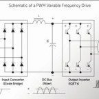
Three-phase utility power goes to the VFD front end, the rectifier section, which converts the ac at the input to a pulsating dc. The pulsating dc is subsequently filtered to remove ripple to produce pure dc conveyed via the dc bus to a final inverter stage. The inverter changes the dc to a square-wave output that powers the motor.
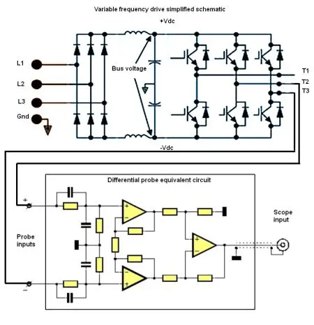
The term “square wave” generally presupposes a 50% duty cycle, but the output to the motor has a varying duty cycle. The three-phase, low-voltage control signal is cabled to the inverter section and applied to the inputs of three power semiconductors that typically generate the inverter output. What is surprising is that these three semiconductors, usually insulated gate bipolar transistors (IGBTs), in three-phase configuration are capable of handling motor loads as great as 500 hp.
The three-phase power is conveyed to the motor, which spins at variable rates and torques determined by the duty cycle and control voltage. The advantage in this arrangement is that the amount of power applied to the motor terminals is determined by duty cycle rather than ac voltage level. So rather than running only at rated RPM, motor speed can vary without temperature rise in the windings. Also, single-phase motors can be powered by small VFDs, which are known as bricks, that weigh only a few pounds.
The PWM switching frequency for a VFD is far higher than the standard 60-Hz utility sine wave. In a VFD it is in the kilohertz range. This relatively high frequency is necessary so the motor will see a relatively smooth waveform. PWM has the advantage that power consumption is low, and that is why speed can be less than rated RPM without excessive heat dissipation. When the electronic switch is off, there is minimal current. And when it is on, there is minimal voltage drop across the switch. Because power is voltage times current, power in excess of what is required to turn the motor is close to zero.
There are several methods used to implement PWM:
•The Intersective method makes use of a triangle waveform, easily synthesized by an oscillator, in conjunction with a comparator. A reference signal is compared to the triangle waveform. When it exceeds the triangle waveform, a logic high state is created. When it is less, the result is logic low. This is the digital PWM signal.
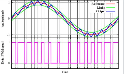
•In the Delta modulation method, the desired signal is integrated and compared to reference signal limits. The PWM changes state at these reference levels.
•In the Delta-Sigma method, a reference signal is established, then the output signal is subtracted from it. The error signal so formed is integrated and when this signal exceeds limits, the PWM signal changes from logic high to logic low or from logic low to logic high.
•Space Vector modulation is used in three-phase VFDs. A reference signal is sampled at uniform intervals. Then the reference signal is synthesized as the average of vectors that have been selected as fractions of the sampling period.
•Direct Torque Control is another method to regulate ac motors. Motor torque and magnetic flux stay within hysteresis limits because the device semiconductors are switched on as required.
•In the Time Proportioning method, a counter fires and is reset at the conclusion of each PWM period. When the counter counts up and its value exceeds a reference digital value, the PWM output changes state from high to low or from low to high. Good resolution is obtained by employing a high-speed counter.
If VFD-powered motor behavior is erratic, the control signal is one of the things that must be verified. As we know, induction motor RPM depends on two parameters, aside from loading. They are the number of poles and the frequency of ac power applied at the input.
In any ac motor, temperature rise is determined by the current through the windings. When the frequency is reduced, the voltage at the winding input must also be reduced to limit the current.
A VFD will maintain a uniform volts-to-Hertz ratio at any frequency. Accordingly, PWM qualities include lower voltage created by narrower pulses that are more numerous during a given time interval. Conversely, higher voltage is created by fewer pulses that are more widely separated. As mentioned above (this is critical), the applied voltage is close to a square wave, but the current through the motor more closely resembles a sine wave. This necessary condition is due to the inductive nature of the load.
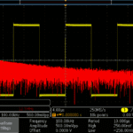
A spectrum analyzer can be used to measure the spectral distribution of these voltages, and the results are revealing. One problem is that typical VFD voltages exceed the upper limits of the instrument inputs. If you do a lot of this work, it may be worthwhile to assemble a step-down transformer that will limit the voltage and isolate it so it is not referenced to ground. The high voltages leave no room for error in this undertaking.
Motor supply voltages are hazardous and they are referenced to but float above ground potential. For this reason, instrumentation used to measure these voltages must be chosen and connected carefully. Maximum input voltages and CAT locations are generally printed on the front panel of any measuring instrument, and it is essential to comply with them.
A bench-type oscilloscope cannot be used to look at floating voltages unless it is equipped with differential probes. These are costly, so most workers choose to employ hand-held, battery-powered oscilloscopes having inputs that are insulated and isolated from one another. The oscilloscope is suitable for checking spectral purity (freedom from harmonics) and voltage balance among the legs.
Similarly, the dc bus carries a floating voltage that is actually higher than the utility voltage at the input, 1.414 times RMS since the rectified output relates to peak-to-peak input. (For a three-phase, 480-Vac VFD, there is 678 Vdc on the dc bus.) The same safety comments apply to the PWM voltage and current at the three-phase motor input.


Leave a Reply
You must be logged in to post a comment.