Most electrical engineers probably are aware that connecting the ground connection for ordinary oscilloscope probes to the wrong part of an ac power line will invite a lot of trouble. Unfortunately the remedies sometimes employed to head off difficulties can cause their own woes. In a lab where I was once employed, the instrument carts each contained isolation transformers from which all the gear on the rack obtained ac power. This certainly solved the scope ground-lead problem but also created circulating currents on the metal frame of the cart that were big enough to give unsuspecting engineers a poke when they touched it. Another tried-and-true technique is to cut off the ground lead from the three-prong ac plugs that most instruments use. This practice may prevent damage from inadvertent ground connections but can also get someone electrocuted in the right circumstances.
With these hazards in mind, a review of the ground lead problem may be useful. To understand the phenomenon, it can also be helpful to first understand a basics about how incoming ac wires are connected at the circuit breaker panel. Unfortunately there are a few misconceptions about these connections that can also lead to hazardous practices.
Residential circuit breaker panels (in the U.S.) is that they are fed with three wires coming down from the secondary of a distribution transformer that typically mounts on a utility pole outside the house. These connections are called L1, L2, and ground. Both L1 and L2 supply 120-V ac. Thus most household appliances get connected via a circuit breaker either to the L1 or the L2 line and ground. Bigger appliances that work from 240 Vac get connected via a breaker to both the L1 and the L2 lines–the two connections add to produce 240 Vac.

A key point to note is that the distribution transformer secondary is configured so the ground connection to the house is actually a center tap from the secondary. The L1 and L2 lines are the connections across the entire secondary. There can sometimes be a misconception that L1 and L2 are 180° out of phase with each other. In that they form a connection across the entire distribution transformer secondary, clearly they are not out of phase with one another. The misunderstanding stems from how the measurement is sometimes made at the breaker panel. Here, the first inclination is to place a ground lead of the probe on the breaker ground, then place the positive probe connection on either L1 or on L2. When measured this way, the ac waveforms displayed for L1 and L2 will appear to be out of phase.
However, recall that the breaker panel ground connection in this case is the center tap of the distribution transformer secondary. Thus the center tap is the negative terminal for one-half of the secondary, but it is the positive terminal for the other half. This is the reason L1 and L2 appear to be out-of-phase when both are measured with respect to an instrument ground connection made to the ground connection in the breaker panel.

Now consider the problem of making a scope ground connection at some point in a power supply circuit. The classic example of the problem often uses connections to a full-bridge rectifier. First consider the case where the rectifier is fed from a transformer. In this case, there is no problem referencing any point in the transformer secondary circuit to ground.
Now suppose the rectifier operates directly off the ac line with no transformer. Placing the scope ground lead on one leg of the rectifier shorts out one of the diodes, a fact easily confirmed by tracing the ground path set up by the probe. This happens because, at least in U.S. electrical systems, the neutral wire connects to ground

at the breaker panel. When one of the bridge diodes is grounded, the full line voltage is applied across one of the other diodes in the bridge. The usual result is an overloaded bridge that quickly fails. Similar overloads and failures befall other kinds of power circuits when components are accidently shorted to ground because of accidental shorts through the scope probe. Scope circuits, too, can experience overloads because of these accidental shorts.
 The typical way of avoiding accidental shorts via probe grounds is to use a battery powered scope; scope ground is no longer the same as ac ground. Another approach is to use differential scope probes. Differential probes measure the voltage difference between two input points in contrast to a single-ended probe, which measures input voltage relative to ground. A differential probe uses a differential amplifier to subtract the two signals, resulting in one differential signal presented to the input of the oscilloscope.
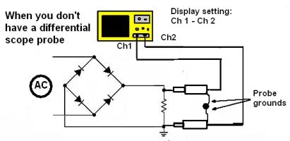 Finally, there is a way to simulate the action of a differential probe using two oscilloscope channels and two probes, one feeding each channel. Here one probe is used for the signal of interest while the other probe is used what would ordinarily be the ground connection; the ground connections of the two probes are typically connected together but not to the circuit under investigation. The scope is set to display the difference between the two channels. This difference signal approximates what would be displayed from a single differential probe in the same circumstance.


Leave a Reply
You must be logged in to post a comment.