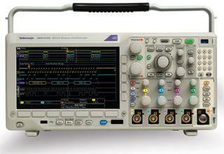
The vector network analyzer (VNA) is an advanced member of the oscilloscope family of electronic instruments. The DUT may be as simple as a single resistor or conductor. The VNA can also operate as a time domain reflectometer, measuring the distance to and nature of a fault, impedance anomaly, complete break or short in a transmission line that is buried, aerial or on the reel.
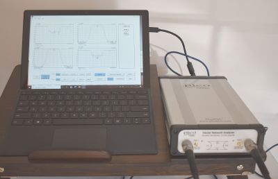 A bench-type VNA is more expensive than an oscilloscope or spectrum analyzer, but Pico offers two VNA models that are PC-based. As such, they make use of an owner-supplied PC’s processing and display capabilities. Pico furnishes the software free of charge, downloadable from www.picotech.com/downloads. The user guide is likewise free. Even if you haven’t purchased the instrument, you can install and use the software in the demo mode to get a good idea of how the instrument displays and functions on you PC.
A less capable instrument is the scalar network analyzer (SNA), which measures network amplitude properties only. The VNA measures amplitude and phase properties. Pico offers two PC-based models, the Pico VNA 106 6-GHz model, available online for $5,995, and the Pico VNA 108 8.5-GHz model priced at $8,225. They are substantially the same except for the different upper frequency limits.
VNA’s are used primarily at high frequencies, although specialized models also cover frequency ranges as low as 1 Hz. These instruments are used for open-loop stability analysis and to characterize audio and ultrasonic components.
The most common task for a VNA is to measure S-parameters of two-port networks such as amplifiers and filters. S-parameters (scattering parameters) describe the electrical behavior of linear electrical networks when undergoing steady-state stimuli by electrical signals. S-parameters stand in contrast to Y-parameters, Z-parameters and others. S-parameters do not use open or short-circuit conditions to characterize linear electrical networks. They use instead matched loads for this task. For this reason, they are more suitable at high frequencies where opens and shorts are less appropriate.
Networks of components such as resistors, capacitors and inductors may be characterized in terms of gain, return loss, voltage standing wave ratio, reflection coefficient and amplifier stability. Scattering pertains to the ways in which voltage and current in a transmission line are modified upon encountering a discontinuity. An example is when an electrical wave meets a variation in the line’s characteristic impedance.
S-parameters are applicable primarily in RF and microwave networks. VNAs focus on them primarily in characterizing two-port networks, but other configurations with an arbitrary number of ports may be characterized as well.
 The most basic VNA consists of a signal generator, test set, one or more receivers and a display. Originally these were separate units, but today they are built in a single enclosure with a common power supply. The signal generator supplies the test signal, which may be swept. Advanced VNAs contain two built-in signal sources, which are needed for specialized applications, including a mixer test, where two discrete tones are required.
The test set applies the signal generator output to the DUT and it feeds the signal-to-be-measured to the receivers. Frequently, a reference signal is used for enhanced measurement accuracy. It serves as a phase reference in the receivers. A VNA will have one or more receivers connected to its test ports. The receiver measures the signal’s amplitude and phase.
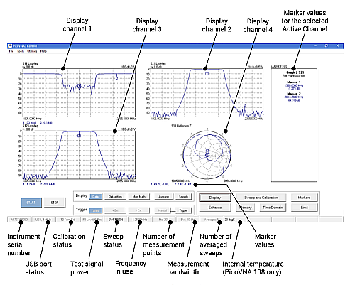
In the display section, reflection and transmission data are presented so they can be interpreted in a meaningful way. Linear and logarithmic sweep, linear and log formats, polar plots and Smith charts are all part of the display, which may also include trace markers, limit lines and pass-fail criteria.
Like the oscilloscope, spectrum analyzer, and other electronic test equipment, the VNA requires periodic calibration. This is because of gradual component aging and physical changes that take place within the enclosure. The calibration takes place yearly and usually involves sending the instrument back to the factory or to an authorized service provider. A new calibration certificate is issued and a sticker attached to the outside of the enclosure, stating when the next calibration is due.
A VNA, because of its great sensitivity and the need for accurate results, is also field calibrated, typically before each measurement or set of related measurements. The purpose of these field calibrations is to correct for errors intrinsic to the current measurement. The errors may arise from ambient temperature changes, line-voltage variations, or the characteristics and orientation of cables, adapters and test fixtures. Field calibration may be needed as frequently as several times in an hour. The process is at once straightforward and exacting. For the Pico VNA it is fully outlined in the user guide.
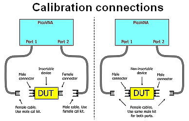
Before undertaking a calibration, the instrument should be connected to the PC and powered up for about 30 minutes. In performing the calibration, if the DUT is insertable (one female and one male connector) two kits are required. If the device is non-insertable, a single kit is required.
With the DUT connected to Pico Ports 1 and 2 and the software installed in the PC, in the main menu select Tools>Calibration kit. Then click Load P1 kit, select data for the Port 1 kit and click Apply. Do the same for the P2 kit.
The next step is to set up calibration and display parameters in the calibration window and display set-up window. Fill in the fields as shown in the user guide. For different types of measurements, different calibration bandwidths and calibration powers can be chosen. Refer to the table in the user guide. As you can see, the field calibration process is straightforward.
The Pico 108 PC-Based VNA has an operating frequency range of 300 kHz – 8.5 GHz. Its dynamic range is up to 124 dB and the frequency resolution is 10 Hz.
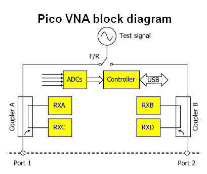
The Pico VNA incorporates four integrated receivers with a maximum bandwidth of 140 kHz. Couplers are wideband bridge components, the purpose of which is to provide two-way directivity. ADCs sample the IF signal and the sample data is processed by a controller, resulting in I and Q components.
Software in the PC enables processing, creating time and frequency domain displays. The VNA contains a tunable RF source. Its output divides into two paths. The coupler output feeds into the Port one receiver where magnitude and phase are measured. The other portion of the signal is conveyed through the DUT to Port two and its phase and magnitude are measured. Port one and two measurements are referenced to the receiver, and spurious variations are removed. Another purpose of Reference one and Reference two receivers is to enable phase measurements.
The test signal is also applied to the DUT output. The Port two receiver measures the reflection from the DUT output port, and the Port one receiver measures the reverse transmission through the DUT.
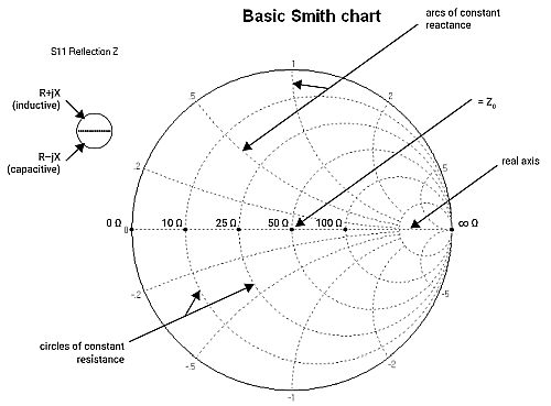 A Smith chart, which appears in the Pico VNA opening widow, is used to display input and output parameters, and it also permits the user to tweak field calibrations.
Phase measurements are important in matching systems to obtain maximum power transfer. Maximum power transfers through complex impedances when the load impedance is the complex conjugate of the source impedance. In resonators, phase measurement is critical in oscillator design. Oscillation arises is feedback circuits when signals at both ends of the loop are in phase. To attain stable oscillation and minimize phase noise, unity gain and in-phase performance close to the center frequency of the resonator are required. In the microwave and adjacent regions, these exacting requirements can best be met by making use of the VNA.


Leave a Reply
You must be logged in to post a comment.