A plus times a plus is a plus. A plus times a minus is a minus. A minus times a plus is a minus. A minus times a minus is a plus.
Because none of these operations results in a negative product, we must confront the hard reality that the square root of a negative number does not exist. And yet, √-1 appears as an intermediate step in many mathematical computations, specifically in electrical engineering. Recognizing this fact, multiples of √-1 have been called “imaginary numbers.”
The gateway to the realm of imaginary numbers is the lower-case j, and it is widely used in electronics. A case can be made that lower-case i would make more sense, but j is used only to avoid confusion because i traditionally has represented current. (It originally denoted intensity.) The relevant terminology is j operator.
In electronics, the j-operator signifies the counter-clockwise rotation of a vector. A vector is the non-scalar graphic representation of a complex number, which is made up of a real number and an imaginary number. The real number is depicted by the length of the line that represents the vector, and the imaginary number is depicted by the angle of that line with respect to the X- and Y-axes.
In electronics, all this comes into play when an ac circuit contains a load that is all or partly capacitive or inductive. The frequency is not changed, but the phase of the current passing through the load (and hence throughout the circuit including inside the generator windings) is shifted with respect to the applied voltage.
There is a lot of misunderstanding about how to handle imaginary numbers in electronics. Take this question recently posted on Reddit, for example: In my physics class that I took last semester we learned about RLC circuits and my teacher sort of handwaved away the imaginary part of the voltage, saying “we only care about the real part.” Is this totally true or is there just a deeper rabbit hole he didn’t want to get into for the purposes of our class?……….. for (circuit) Q we have a real and imaginary part. So what does the imaginary part mean in reality? If we tried to see it on an oscilloscope, per se, could we? Could we have some sort of device that would measure charge or voltage in the complex plane? Or does none of this matter because the imaginary part is just an artifact of the mathematics that doesn’t have any real meaning?
So perhaps a quick review of the J parameter in electrical engineering wouldn’t be wasted. In an equation describing circuit behavior, the imaginary part denoted by the J operator, plus the real part, describes the phase relationships between voltage and current as well as the waveform that will display on an oscilloscope. To see the phase relationship on a scope, you would need to display both the voltage and current of interest. The lag and lead between them constitutes the phase relationship.

Imaginary terms arise from the fact that ac impedance is represented as a complex, vector quantity. It is displayed on a polar coordinate system where quadrants one and two correspond respectively to
passive inductance and passive capacitance. The impedance vector consists of a real part, resistance (R), and an imaginary part, reactance (X).

The two forms of reactance are inductive (XL) and capacitive (XC). The quality factor (Q) and the dissipation factor (D) also have resistance and reactance in their definitions. These parameters serve as measures of reactance purity. When Q is larger or D is smaller, the quality is better. Q is defined as the ratio of the energy stored in a component to the energy dissipated by the component. D is the inverse of Q. D is also equal to “tan δ”, where δ is the dielectric loss angle (δ is the complementary angle to θ, the phase angle). Both D and Q are dimensionless.
The instantaneous voltage and current at a point in an ac circuit can’t be assumed to be in phase. So they have be expressed as the real part of a phasor and the complex sinusoid ejωt,![]() V and I are the complex amplitudes or phasors. The phasors can also be written as magnitudes and phase angles,
V and I are the complex amplitudes or phasors. The phasors can also be written as magnitudes and phase angles,  Of course, phase angle comes into play when power is computed. The instantaneous power in a circuit element is simply p(t) = v(t)i(t). The product of the two cosines produces a constant (dc) term and a time-varying term at twice the frequency,
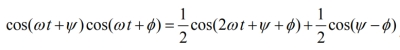 The time-averaged power flow comes from integrating the instantaneous power over one cycle, which retains the dc term while the 2wt term averages to zero:
 ![]() The average, real power flow is the real part of the complex power, Pavg = Re{Pc} = Re{½VI*}.
The average, real power flow is the real part of the complex power, Pavg = Re{Pc} = Re{½VI*}.
The phase angle and instantaneous voltages and currents in real ac circuits are actually more complicated than what these equations express because there are forward and reverse components traveling through real ac circuits. These can be quantified but add quite a bit of complexity to the analysis.
Getting back to inductor and capacitor impedances, recall these entities can be written in polar form: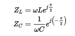 A point to note about these relationships is that the real part of Z for both components vary with frequency. The imaginary parts (ejπ/2 and e-π/2) are constant. This shows that in an inductor, voltage therefore leads the current by π/2 and in a capacitor, the voltage lags the
current by π/2. And this relationship doesn’t change with frequency.

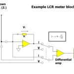
Interestingly, some modern LCR meters can show this relationship directly. A case in point is the Keysight Technologies E4990A Impedance Analyzer.


I have always understood that lower-case I represents the value of a current which varies with time, at some point in time. That is I represents instantaneous current.