An arbitrary function generator (AFG) produces oscillating energy that takes the form of periodic or one-shot waves. We should begin by asking: What is the difference between an AFG and an arbitrary waveform generator (AWG)? Also, what is meant in these contexts by “arbitrary?”
Arbitrary as applied to waveform generation means that the user can program the device to make a waveform by specifying it mathematically. Many waveforms can be created, and they are not confined to a specific internal library. The underlying idea is the relationship between function and signal. Actually, they are the same. Function is a word used by mathematicians, while electronics engineers use signal. (Signal is the electrical energy that appears at output terminals. If it oscillates, it is a wave. A waveform is the graphic depiction of that wave, typically in a time-domain display plotted against Cartesian coordinates.)
 An AWG is generally based on Direct Digital Synthesis (DDS). DDS creates arbitrary waveforms from a single, fixed-frequency reference clock.
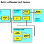
A basic DDS circuit consists of a frequency reference (often a crystal or SAW oscillator), a numerically controlled oscillator (NCO) and a digital-to-analog converter (DAC). The reference oscillator provides a stable time base for the system and the clock to the NCO which outputs a discrete-time, quantized version of the desired output waveform whose period is controlled by the digital word in the frequency control register. The DAC converts the sampled, digital waveform to an analog waveform. The output reconstruction filter rejects the spectral replicas produced by the analog conversion process.
DDS is used in many applications other than AWGs and related instruments. Examples include local oscillators in communications systems, mixers, modulators, sound synthesizers and phase-locked loops.
A DDS is superior to the analog phase-locked loop because of the precise interaction between the inherently stable NCO, frequency control register and the reference oscillator. One aspect of DDS-based AWGs is that their digital nature lets them incorporate multiple channels that can operate simultaneously. This permits copious functionality including accurate phase offsets and frequencies that can be set to desired ratios.
There is a wealth of other capabilities, such as the ability to continuously sweep the frequency of the output waveforms, using a voltage-controlled oscillator. Start and stop frequencies can be user-determined in the manner of a spectrum analyzer.
Synthesized waveforms invariably have upper-frequency limits, for a sine wave in the low gigahertz range, and still lower for non-sinusoidal outputs. These upper limits are in part due to cabling, which is typically coax with 50- or 75-Ω BNC terminations.

AWGs are ordinarily equipped with a built-in library of signals, which may, in the case of noise, be dynamic. Available waveforms include sine, square, pulse, ramp, dc, noise, sin x/x, Gaussian, Lorentz, exponential rise, exponential decay, Haversine, and cardiac.
Tektronix offers an internal AFG as an option in the MDO3000 oscilloscope, and this is an extremely worthwhile feature. The hookup consists of a BNC cable run from AFG Out on the back panel to an analog channel input or the RF input, using an RF adapter, on the front panel. Then, pressing AFG with the channel activated, the available waveforms appear in a vertical menu and they may be individually selected by turning Multipurpose Knob a.
The second menu selection is Waveform Settings. They are not identical for all waveforms. When Sine is displayed, the user can select Frequency/Period, Amplitude/Offset and High Level/Low Level by turning Multipurpose Knobs a and b. For dc, only Offset is applicable, and for Noise there is no such thing as frequency, although peak-to-peak amplitude can be set anywhere from 20.00 mVpp to 500.00 mVpp.
The final important selection in the AFG menu is Output Settings, accessed by pressing the appropriate soft key. This brings up a vertical menu on the right. The top menu selection is load impedance. The soft key toggles it between High Z, which is used most of the time and is the default setting, and 50 Ω, which is used only when necessary to match a low-impedance load.
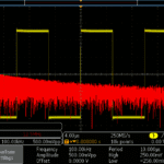
The second selection in Output Settings is Add Noise, expressed as a percentage. With any waveform other than noise displayed, you can see how this works by turning Multipurpose Knob a. Notice that around 20% triggering is lost. Add noise is useful in trying out noise mitigation techniques, notably Bandwidth Limiting and Signal Averaging.
The third menu selection permits the user to define the Auxiliary Out port on the back panel. Setting it to AFG, you have access to two waveforms on separate channels. This is just what’s needed to try out Dual Waveform in the Math mode.
The output of a related instrument, the digital pattern generator, consists of a waveform that varies between two voltages that represent high and low logic states. A simple hand tool that does this is the pulser, which, in conjunction with a logic probe that reads the signal, is capable of creating logic states in digital circuits and components.
A digital pattern generator goes far beyond that. It can produce a repetitive or, when triggered, single-shot signal and there is an extensive user interface.
Like PC-based oscilloscopes and spectrum analyzers, digital pattern generators are available as modules that are connected to a user-supplied PC, which defines, stores and analyzes the digital patterns, and also functions as a user operator interface.
Various digital devices incorporate different operating voltages, so the digital pattern generator must output the correct signal family with respect to the equipment and application contemplated. Digital pattern generators are capable of outputting repetitive signals at the desired frequency. They may use external clock and trigger signals to execute upon a predetermined external event. Video digital pattern generators create test patterns specific to the video format. Prices for some of these instruments exceed $10,000.

Leave a Reply
You must be logged in to post a comment.