Signal generators are subdivided into categories that include arbitrary function generators (AFGs) and arbitrary waveform generators (AWGs). The word arbitrary denotes a user’s ability to create waveforms beyond the permanent contents of the instrument’s internal memory. Besides AFGs and AWGs, there are RF and microwave signal generators, pitch generators, digital pattern generators, and more. Typically, bench-type ac-powered stand-alone units have BNC ports permitting connection to separate display and analysis instruments such as oscilloscopes and spectrum analyzers. Signal generators usually have small flat screens for monitoring the output.
It would be easy to salvage or fabricate RC or quartz crystal oscillators to make your own instrument, but the resulting device probably wouldn’t have the features available in a factory-made 50-MHz model with 256K-point 14-bit resolution, arbitrary function capability, precision rise and fall times for square and pulse waves, external time base for synchronizing multiple units, AM, FM, PM, FSK and pulse-width modulation, with waveform creation software for a user-supplied PC.
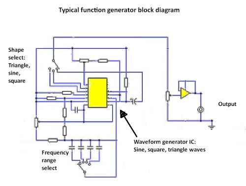 An AFG is less expensive than the AWG, but it is sufficient for most applications outside of an exacting laboratory. The AFG has a smaller built-in library of waveforms and a little less capability for synthesizing user-created waveforms, but it is stable and fast for switching frequencies and exporting the results.
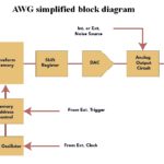
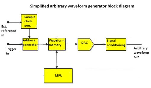 AFGs and AWGs, as opposed to old-style audio oscillators, include the ability to generate and store almost any waveform that the operator can imagine. Waveform and instrument designs are both digital. The waveform, along with its specifications, can be stored and later recalled in a variety of digital formats. Subsequently, wave shape adjustment in a user-supplied computer can be accomplished using the appropriate software.
Modern digital oscilloscopes generally contain a built-in AFG. While lacking some of the features in a modern autonomous signal generator, front panel controls permit the operator to select any of a dozen or so waveforms in addition to arbitrary waveform creation. Also, frequency (period), amplitude and offset can be adjusted. Output settings include high-Z and 50-Ω load impedance, the addition of 0 to 100% noise, and auxiliary-out triggering.
There are a number of related instruments, such as RF, microwave, vector signal, digital pattern, pitch, audio and video signal generators.
RF signal generators produce continuous wave (CW) tones that can be tuned and modulated to simulate a radio broadcast. Modulation types are AM, FM, phase modulation and pulse modulation. The type and degree of modulation can be set by means of front-panel controls.
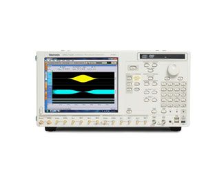
Vector signal generators produce digital signals for the purpose of testing communications systems. These instruments generate digitally modulated RF signals using various modulation techniques including QAM, QPSK, FSK, BPSK and OFDM.
Digital pattern generators output binary logic signals comprised of logic high and logic low, usually 1 and 0 respectively. These signals can be injected into stand-alone ICs and embedded systems for testing and validation.
Pitch generators range from inexpensive beepers and wands that telephone technicians use for locating wires in densely-populated punch blocks to audio sweep generators for viewing signals in the frequency domain. Pitch generators may be digital, intended to measure jitter, bit errors and clipping. Additionally, metadata associated with various digital audio formats can be correlated. Multipitch generators superimpose two or more frequencies to detect intermodulation distortion.
Finally, a video signal generator is used in computer monitor and television servicing. The signal may be inserted at various stages to simulate faults and to evaluate the fidelity of a CRT or flat screen and supporting circuitry. Of course, the output contains synchronization signals – vertical and horizontal sync for analog and characters for digital sets. Composite video, NTST and PAL, includes the color burst.
Analog troubleshooting and diagnosis typically make use of an AFG or AWG in conjunction with an oscilloscope. This combination is highly effective for locating faults in electronic equipment, especially in AM/FM receivers, televisions, transmitters and radar equipment.
As an example, consider repairing a high-end FM stereo receiver. Ideally, you’ll have product documentation including schematic, block diagram, and parts list with component values and parts numbers. If that information is not unavailable, it will be necessary to follow wiring and circuit board traces to locate the stages. Their placement may not seem logical because the designers must work with cooling, EMI, inductive/capacitive effects and characteristic impedance.
There is always the potential for introducing a new fault when troubleshooting or making a repair. As an example, CMOS circuitry has become ubiquitous in modern electronics. It is made up of complementary pairs of P-type and N-type insulated-gate semiconductors. The input signal for CMOS consists of a small fluctuating electric charge, which is present at the thin insulating layer. These devices consume little power and have high noise immunity, but they are instantly destroyed with no visual indication if a sufficiently high static charge is applied at the terminals. So there’s a need for great care during handling, probing and soldering.
In beginning the signal tracing operation, do not expect to see a signal at the antenna. There the amplitude of the signal is below the range or ordinary measuring instruments. The place to begin is at the output of the tuner. It is unlikely that faults will develop there. The tuner is usually in a separate grounded enclosure, and if it needs service, it generally goes out to a specialized shop because of its sensitive nature.
The tuner output could serve as the source for signal tracing throughout the receiver, but it is better to disable the tuner by unhooking the antenna and then to connect the signal generator at the tuner output. That is because the signal generator produces an ideal uniform tone, which can be meaningfully evaluated at points downstream. Moreover, using the signal generator, the tone can be modified and injected at different points.
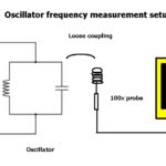
Early in the process, check the output of the local oscillator. Its purpose is to combine with the RF, making a lower, more manageable intermediate frequency (IF) carrier, which is still modulated. As the user tunes to various radio frequencies, the oscillator frequency changes so that there is a single IF for all broadcast stations. In the old days this was accomplished by means of a double-gang capacitor, but now it is done electronically. One of the advantages of the IF, aside from a more user-friendly frequency, is that with a single frequency for all stations, coupling and filtering between stages is simplified. Therefore, good design consists of getting out of the RF region fairly soon, and, for a big set, having many IF stages.
Assuming the oscillator is working, you can begin signal tracing. The most fundamental protocol is to leave the signal tracer at the tuner output and probe downstream, observing the oscilloscope trace at the output of each stage. When the trace disappears, you’ve found the bad stage. Using the half-splitting technique, you can start in the middle and save a few steps.
There are some variations in the above procedure. The signal generator and oscilloscope can be configured to check two or more stages together. If you are working with a stereo set that has one bad channel, various tests will suggest themselves. Also, if an identical good working set is available, displays can be compared at identical outputs.
The above observations pertain to simple faults where there is a single dead component. In the real world, there may be distortion, noise, intermittents, multiple faults, power-supply problems, etc. Television servicing is a whole different world. Besides audio, there are video signals, synch, color bursts, and specialized circuitry unique to each make and model. Many TV schematics include graphics at various points, picturing the oscilloscope display of a good working set.


Leave a Reply
You must be logged in to post a comment.