When you are trying to get an accurate idea of waveform qualities from a scope display, the display settings are quite important. So it can be helpful to review the setup process in widely used scopes such as a Tektronix MDO3000.
Display style and persistence in this instrument can be accessed by pressing the Acquire button with or without an analog channel input turned on and with or without a signal present at the input. To see the effect of display style and persistence controls, a Tektronix AFG31000 Arbitrary Function Generator in the Basic Mode can be cabled to the oscilloscope and sine wave connected via two BNC cables to channels one and two in both instruments.
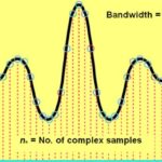
Having pressed Acquire on the oscilloscope front panel, the horizontal Acquisition menu appears below the display. Pressing the soft key associated with Waveform Display, the vertical menu appears at the right side of the screen. The top soft key toggles Dots Only off and on. When this function is on, interpolation is disabled so the trace is seen as at the analog-to-digital converter (ADC). The dots may be difficult to distinguish due to record length, clock speed, persistence, waveform scaling and other variables.
When Dots Only is off, one of several types of interpolation become active. There are numerous types of interpolation. To create a readable display, other than Dots Only, three types of interpretation used in an oscilloscope are pulse, line and Sin(x)/x:
Pulse draws horizontal lines to succeeding display points in the direction of next in the series. Then, a step pattern is created by drawing a vertical line to the succeeding display point. Line simply draws a straight line between two display points. Sin(x)/x interpolates between pairs of display points with a sine-like curve, its amplitude dependent upon the distance between the points.
These interpolation methods create new display points, as opposed to actual new sample points. In these simple types of interpolation, the oscilloscope’s waveform data record is unchanged. The two interpolation variants should not be confused.
Persistence can be toggled off and on by means of the second vertical soft key. Persistence has its roots in the old analog CRT-type oscilloscopes, in which a phosphor coating inside the screen caused the bright spot from the electron beam to persist, making for a more readable trace. In contrast, the method used to create persistence in a modern flat-screen digital oscilloscope is totally different. Analog scopes need persistence because a CRT image goes away the instant there is no electron beam. Of course, the digital storage oscilloscope retains trace information in memory, providing non-chemical persistence.
In the Waveform Display Menu, Persist Time allows the user to set the length of time waveform data remains on the screen. Multipurpose Knob a adjusts Persist Time from 50.0 msec to 10 seconds, and it can be set at infinite. Persistence can also be set at Auto, which is used in most applications. The bottom menu item clears persistence.
Variable persistence is useful for displaying infrequent signal anomalies, particularly glitches. For a specific period of time, variable persistence accumulates record points. In accordance with the time interval, the number of record points increases. Progress in the direction of infinite persistence is halted only when an acquisition display setting is changed.

Horizontal position is set to zero seconds when the Horizontal Position knob is pressed and Delay is toggled On. If Delay is off and the Horizontal Position knob is pressed, horizontal position is fixed at 10%.
The vertical controls are used to select waveforms, adjust the waveform vertical position and to scale and establish input parameters. Waveforms are selected, added or removed by pressing the channel menu buttons as needed and pressing the soft keys associated with listed menu items. The instrument rescales and repositions the displayed waveform(s) in response to any new control settings. This is what is displayed when the Run button is pressed. These new settings form the succeeding acquisition. It may be clipped. To restore the displayed signal, it can be again repositioned.
Throughout, the Math waveform, cursor and automatic measurements are retained. Input parameters are also set using the vertical controls. First, it is necessary to press the applicable menu button(s) to display the vertical menu pertaining to the selected waveform, which can also be chosen or canceled by pressing the channel buttons.
For readability, press the soft key associated with Coupling in a channel menu. DC coupling displays ac and dc components. AC coupling blocks the dc component so low-amplitude ac waveforms and ripple in a dc power supply output can be seen.
In the same menu, the soft key associated with Termination toggles between 50 Ω and 1 MΩ input impedance. It is necessary to make this selection based on the connected load. An impedance mismatch, especially when high frequency signals are conveyed, results in harmful data reflections and signal corruption.

The third menu item is Invert, and like others, it is toggled by pressing appropriate soft keys. The display is changed from normal to invert the signal in the preamplifier. This could be accomplished externally by means of an electrical four-way switch, but don’t even think about it unless you want an intense reverse-polarity arc fault.
The fourth menu item is Bandwidth, which allows the user to limit the bandwidth of the signal at the input. Choices are Full Bandwidth, 250 MHz and 20 MHz. (250 MHz is not available in lower bandwidth models.) The rationale for temporarily limiting the instrument’s bandwidth is to reduce noise that may obscure a waveform as displayed. It works because thermal noise is a broad-spectrum phenomenon that appears less intense when high-frequency components are suppressed. Of course, bandwidth limiting is not useful when the signal under investigation is above the frequency limit.
Waveform averaging, also known as signal averaging, is an excellent complementary noise reduction strategy without the disadvantages in bandwidth limiting. This approach takes advantage of the fact that in successive cycles a periodic waveform is mostly unchanged in amplitude and frequency, whereas thermal noise, a random phenomenon, fluctuates and changes from cycle to cycle. If the averages of successive cycles are displayed, the true signal is re-inforced while thermal noise loses out.
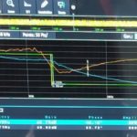
If you press AFG in the oscilloscope and the soft key adjacent to Waveform, Multipurpose Knob a can be used to display a sine wave. Then, press the soft key associated with Output Settings and add 30 to 50% Noise to the sine wave. The trace becomes noisy and at a certain point triggering is lost and the signal becomes chaotic and indistinct.
Pressing Mode in the Acquisition Mode menu allows the user to activate Average. Then, Multipurpose Knob a determines the number of waveforms that are averaged, ranging from 2 to 512. As more waveforms get averaged, the noise content diminishes and the trace becomes clear and distinct.
Probe Setup defines probe parameters. In the vertical menu, select voltage or current for the type of measurement. Generally, an oscilloscope is optimized to perform a broad range of voltage measurements, but it is also possible to measure current. For this, a current probe is required, and the oscilloscope must be configured using the Probe Setup menu.
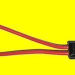
The oscilloscope current probe resembles the familiar electrician’s clamp-on ammeter. The oscilloscope current probe is smaller. As in the Amprobe (trade name), the oscilloscope current probe has jaws that open to accept a conductor, which can be coiled to pass through the jaws two or more times to multiply low-level, out-of-scale current.
An interesting feature of the oscilloscope current probe is that it can be used in conjunction with a voltage probe in a separate channel to measure power. With the oscilloscope in the Dual Waveform Math mode, choose X (multiply) as the operator.
Finally, when using voltage and current probes together, Deskew makes display and measurement adjustments for channels that have differing propagation delays.


Leave a Reply
You must be logged in to post a comment.