Learn the basics of back EMF, how to measure it, and the advantages and disadvantages of different motor types.
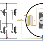
In Part 1 of this FAQ, we looked at brushed DC and brushless DC (BLDC) motors, with the latter having some similarities to a permanent-magnet synchronous motor (PMSM). The simplified PMSM diagram in Figure 1 resembles the diagram presented in Part 1 for the BLDC motor minus the electronic commutation circuit. Subtle yet significant differences between the two, however, manifest themselves in the BLDC motor having a sinusoidal back electromotive force (EMF) while the PMSM has a trapezoidal back EMF.

What’s back EMF, and how can I measure it?\
Back EMF (VBEMF) is the voltage generated by a rotating motor in its dual role as a generator and is proportional to speed. Figure 2a shows a simplified model showing VBEMF, series resistance (RS), and series inductance (LS). To measure VBEMF, disconnect the motor from any input power source, hook up your oscilloscope to the motor terminals, and spin the motor at a known speed. You can directly observe the VBEMF on the oscilloscope (Figure 2b) because with no current flowing, RS and LS won’t contribute any voltage drop.

Often, you want to measure back EMF during motor operation to obtain speed and position information. In a typical three-phase BLDC motor electronic-commutation scheme, at any given time, only two phases carry current, and a motor controller can measure back EMF on the third, unenergized phase. Alternatively, you can measure series current I and calculate the back EMF:
![]()
For more, see “Lenz’s Law and Back EMF” in Motion Control Tips.
What are the disadvantages of PMSM or BLDC motors?
Regarding DC motors, sometimes it’s convenient to vary the field strength, which you cannot do with permanent magnets. Given constant field strength, a conventional DC motor operates in a constant-torque mode up to the speed at which the motor’s back EMF approaches the input voltage. At this point, reducing the field current reduces the back EMF, and the motor can operate at higher speed but at lower torque, establishing a constant-horsepower mode. This mode can be useful in applications such as machine tools, where a tool can operate with constant cutting power even as material densities change.
For any permanent-magnet motor, permanent-magnet supply-chain issues are becoming critical, as highlighted in this U.S. Department of Energy report. Consequently, research is ongoing to find alternatives. Options have long existed, including the brushed DC motor discussed in part 1, albeit with drawbacks. Another alternative is the wound-rotor synchronous motor (WRSM). Figure 3 shows brushes and slip rings carrying DC current to and from a WRSM’s rotor windings. The slip rings and brushes lack the arcing and flashover risk of the brushed DC motor commutator, yet they remain subject to mechanical wear.

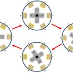
Another option is the AC induction motor. In Figure 4 left, the rotor consists of a conductive loop surrounding a laminated iron core. When the shaft rotates, the stator magnetic field induces AC currents in the loop, causing magnetic-polarity reversals in the rotor core, as shown in the oblique view on the right. The rotor tries to keep up with the stator’s rotating magnetic fields, but it never succeeds. Were it to do so, the conductive loop would no longer be cutting through the stator’s magnetic field, and its current would drop to zero. Consequently, the motor operates at a “slip”— a few percent shy of synchronous speed.

Instead of one conductive loop, a typical three-phase induction motor has multiple conductors arranged in a configuration resembling a squirrel cage, and it’s often called a squirrel-cage motor. With no commutator or slip rings, this motor has long been a reliable workhorse. It’s optimal when running at full speed and load in applications such as periodically replenishing a water tower because the motor is driving a constant-speed pump. Its efficiency takes a hit when operating at varying speeds and loads—driving a variable-speed pump that maintains constant water pressure despite varying demand, for example, or serving as a traction motor in an electric vehicle.
What else should I know about motors?
In Part 3 of this series, I’ll describe an electric motor that has no permanent magnets, no commutator, no brushes, no slip rings, and no squirrel cage. We’ll also look at the role of modern drive electronics in making this motor practical and in boosting the performance and efficiency of other motor types. Finally, we will look at power and efficiency measurements. Meanwhile, EEWorld has just produced a series of presentations on motor-drive design, which you can view on demand here.
Related
How do I choose an electric motor, and how do I test it? Part 1
How do I choose an electric motor, and how do I test it? Part 3
How do I choose an electric motor, and how do I test it? Part 4
Driving brushed and brushless DC motors
Motor fundamentals and DC motors
Webinars: Motor Drives Design
The brushed DC motor: Still a very viable option, Part 1: Operation
The brushed DC motor: Still a very viable option, Part 2: Applications
The brushed DC motor: Still a very viable option, Part 3: Drivers
FAQ: What’s the difference between BLDC and synchronous AC motors?
Comparing stepper and brushless dc motors


Leave a Reply
You must be logged in to post a comment.