Motors follow the path of less reluctance to rotate. Thus, you need timing of applied power to get them moving.
Part 1 and Part 2 of this FAQ looked at brushed and brushless DC motors, permanent-magnet and wound-rotor synchronous motors, and induction motors. These motors all have drawbacks, including mechanical wear of commutators, slip rings and brushes, permanent-magnet supply-chain issues, and efficiency issues at partial speeds and loads.
You mentioned a motor that avoids these drawbacks. What is it?
It’s the switched reluctance motor (SRM).
What’s reluctance?
It’s the magnetic analog of electric resistance. Figure 1a represents a state of high reluctance. The iron rotor holds its position only because someone’s holding it. Remove the hand, and the rotor seeks out a low-reluctance state, aligning with the stator poles (Figure 1b).

How do we turn reluctance into rotation?
In Figure 2 — three-phase SRM — each phase is wired, as shown on the right. We want to sequentially energize each phase in a way that successive rotor teeth seek out paths of low reluctance to cause rotation. Because the rotor is iron — not a permanent magnet — the phase polarities need not reverse.

What sequence do we use?
In Figure 3, energized phase AB attracts rotor teeth 1 and 3 at the top, inducing clockwise rotation. When the rotor assumes the position shown on the right (minimal reluctance for phase AB), phase AB de-energizes, and phase CD energizes, attracting teeth 4 and 2. Next, phase CD de-energizes, phase EF energizes, attracting teeth 3 and 1 (bottom), and the cycle repeats (left). A four-tooth rotor in a three-phase motor rotates one-quarter turn for each AB-CD-EF sequence.

How do we switch the phases on and off?
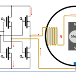
A bridge circuit similar to that used to drive a brushless DC motor in part 1 can handle the power switching. Figure 4 shows one circuit for driving phase AB. Identical circuitry drives the other two phases.

The challenge with the SRM lies in the control circuitry, which generally requires a precision rotary encoder to provide speed and position feedback as well as a real-time processor or FPGA to run the switching algorithms. Indeed, modern electronic advances have made the SRM a practical solution.
What are the algorithm basics?
The example in Figure 3 uses a simple switching scheme — waveforms with a 33% duty cycle (Figure 5a) energize one phase at a time. More complex switching schemes, such as one with 50% duty-cycle waveforms (Figure 5b), provide better performance —minimizing torque ripple at low speeds while optimizing acceleration, deceleration, and step-load response. Work on optimization is ongoing. See, for example, this paper on optimizing SRM phase-current control and this paper on applying neural networks to optimize SRM efficiency and output power.

About the “switched” in SRM—are there other reluctance motors?
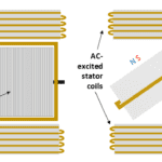
Yes. Synchronous reluctance motors (see here, for example) can operate off the AC line. In fact, some wound-rotor synchronous motors can act as reluctance motors. With the rotor windings disconnected, the rotating fields established by the stator coils continue to attract the iron rotor teeth, causing the motor to spin, although with much lower torque.
Whatever motor we choose, how do we test it?
Figure 6 outlines one test setup. A programmable power supply simulates the AC line or motor-drive input to the motor under test over a range of input voltages and, for AC motors, frequencies. Motors having separately excited field windings require additional inputs. The motor under test drives a programmable mechanical load, with rotation and torque transducers providing feedback to a power analyzer. That analyzer measures various parameters, including efficiency, which is output power (torque times speed) divided by input power.

This approach is good for confirming your motor works. You might need instruments ranging from meters to oscilloscopes to find solutions if it doesn’t. We’ll take a closer look at part 4 of this series. Meanwhile, you can review this technical article from Hioki and this application note from Yokogawa for more on power measurement and analysis.
Related
How do I choose an electric motor, and how do I test it? Part 1
How do I choose an electric motor, and how do I test it? Part 2
How do I choose an electric motor, and how do I test it? Part 4
Driving brushed and brushless DC motors
Motor fundamentals and DC motors
Webinars: Motor Drives Design
The brushed DC motor: Still a very viable option, Part 1: Operation
The brushed DC motor: Still a very viable option, Part 2: Applications
The brushed DC motor: Still a very viable option, Part 3: Drivers
FAQ: What’s the difference between BLDC and synchronous AC motors?
Comparing stepper and brushless dc motors


Leave a Reply
You must be logged in to post a comment.