Bandwidth has an array of meanings, depending on the context. Often, but not always, the term is applicable to a situation where one frequency is superimposed on, mixed with, or modulates a different frequency. A simple and fundamental example is amplitude modulation and its close relatives, frequency and phase modulation.
 When speaking of a broadcast station’s frequency, it is generally the carrier’s frequency that is referenced. The true situation is slightly more complex because, in amplitude modulation, a much lower audio frequency modulates the carrier. The carrier’s frequency is unchanged, but its amplitude oscillates, at any instant relating to the amplitude of the audio signal, which itself varies in amplitude and frequency. The carrier is said to have an envelope, which can be displayed on the screen of an oscilloscope.
When an audio signal is superimposed on an RF carrier, sidebands at the sum and difference of the carrier frequency are produced. The transmitted signal is therefore distributed in frequency over a bandwidth that is equal to twice the highest frequency in the signal. The broadcaster determines the bandwidth of the signal as transmitted by choosing the high-frequency cutoff of the modulating audio.

The AM band is more crowded than the FM band. In the U.S., a regulatory agency, the FCC, allocates a limited bandwidth for each broadcaster so their signals will not interfere. It is the broadcaster’s responsibility to refrain from modulating the carrier with high-frequency tones that would extend the bandwidth beyond statutory limits. Greater bandwidth is permitted for FM broadcasters because FM signals, which do not bounce off the ionosphere but propogate only along line of sight, cover a smaller area. For this reason, most music programming, which requires high-frequency audio, is broadcast via FM. AM is used more for talk radio, where high-frequency response is less critical.
Single sideband, as a transmission technique, has the advantage of using transmitter power and bandwidth in a more efficient manner. Conventional AM consists of the carrier plus two sidebands (additive and difference signals) each of which carry the same information. This unnecessary duplication can be avoided by suppressing one of the sidebands, which can be done using simple filters. Thus, bandwidth and power requirements are reduced in a single stroke. The downside is greater complexity in tuning and demodulation at the receiver.
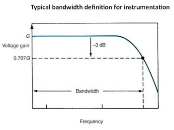 In regard to systems, instrumentation or communications channels, bandwidth has a somewhat different meaning. It is a measure of the highest frequency that can be processed. A 1-GHz oscilloscope, for example, can display signals that do not exceed 1 GHz. But that is not the whole story. As the bandwidth limit is approached, the signal is increasingly attenuated, until it is lost below the noise floor of the instrument. Therefore, in specifying the bandwidth of the instrument, a precise attenuation level must be specified.
The 0 dB level is the oscilloscope’s peak response. Bandwidth of the oscilloscope is the maximum frequency that can get through the front end with less than 70% attenuation, which is -3 dB of the signal at the oscilloscope input. This is for an ideal sine wave. Square waves and similar signals with fast rising and falling edges cannot be conveyed at the full bandwidth of the instrument.
Another related meaning of bandwidth is the maximum rate of data transfer from one point to another. Signal bandwidth and channel noise contribute to this metric. To quantify bandwidth in this meaning, rather than frequency in Hertz, bits (or kbits, Mbits, Gbits) per second are used.
Webhosts and servers use the term bandwidth to denote the amount of data transferred to or from the server or website per unit of time. A link can convey a maximum bit rate, in accordance with its Shannon-Hartley channel capacity.
All spectral bands of a given width carry the same amount of information, regardless of frequency. The bandwidth of a device divided by its center frequency is known as its fractional bandwidth. This quantity is expressed as a fraction or a percentage. The fractional bandwidth of an antenna relates to how wideband it is.

Bandwidth is also a measure of frequencies over which an antenna can receive or radiate electromagnetic energy. The Q factor of an antenna is inversely related to antenna bandwidth. An antenna is chosen on the basis of its bandwidth/Q factor. An antenna with low bandwidth cannot be used successfully in wide-band applications.
For comparison purposes, here are some common antenna types. With center frequencies set at 1 GHz, they are ranked from lowest to highest bandwidth:
• Patch – 0.03 fractional bandwidth
• Dipole – 0.08 fractional bandwidth
• Horn – 1.694 fractional bandwidth
• Spiral – 1.805 fractional bandwidth
Bandwidth and Q are also applicable to resonant circuits in general, i.e. not just those that are antennas. Q is a measure of the quality of a resonant circuit. It is a figure of merit, corresponding to narrow bandwidth, which is usually desirable in a resonant circuit.
Where a resonant circuit contains reactive and resistive components, Q is the ratio of power stored to power dissipated:
Q = PSTORED / PDISSIPATED = I2X / I2R
Simplifying:
Q = X / R
where X = capacitive or inductive reactance
and R = series resistance
This equation for finding Q applies to both series and parallel resonant circuits where the resistance is in series with the inductance. Because X is in the numerator, greater reactance always means higher Q. Because R is in the denominator, greater resistance means lower Q. Because I is squared, it figures prominently in similar equations, but appearing here in both numerator and denominator, it cancels out and does not affect Q or inversely the bandwidth of the circuit.
At the resonant frequency, capacitive and inductive reactances are equal and cancel out. The resistive component comprises the circuit impedance. A lower resistance creates higher Q and lower bandwidth.
At resonance, impedance is maximum in a parallel resonant circuit. Above or below resonance, impedance decreases. At resonance, impedance is minimum in a series resonant circuit. Above or below resonance, impedance increases. These effects are more dramatic when the resistance is decreased, creating a higher Q factor and less bandwidth.
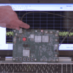
These effects can be demonstrated by connecting an RLC resonant circuit to an arbitrary function generator sine wave at the input. Use a potentiometer so resistance can be varied. Probe the output and connect to an oscilloscope analog input channel. Vary the AFG sinewave frequency to find resonance. Substitute capacitors if necessary. Press Math>FFT to display the circuit output in the frequency domain. Then vary R by turning the potentiometer to observe the effect on Q and bandwidth.
Bandwidth concepts also apply to the display of electrical noise. Besides consisting of irregular fluctuations, noise tends to be broadband in frequency. These two qualities can be exploited to eliminate the effects of noise in test instrumentation.
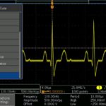
Using a Tektronix MDO3000 Series oscilloscope, we apply a sine wave from the internal AFG and display it via an analog channel input. Then, in the AFG menu, press Output Settings and add 30% noise. This is sufficient to thicken the trace and make the display lose triggering. Because the sine wave is periodic but the noise is random, waveform averaging is highly effective in cleaning up the signal. Press Acquire > Mode > Average. Then, using Multipurpose Knob a, increase the number of waveforms that are averaged until the noise is abated.
Because noise is a broad-spectrum phenomenon, it can be mitigated by temporarily limiting the bandwidth. Press Default Setup and reacquire the sine wave with 30% noise added. Then, press the active channel button. In the horizontal menu at the bottom, press Bandwidth. In addition to Full Bandwidth, it can be reduced to 250 MHz and 20 MHz. 250 MHz has little effect but cutting the bandwidth to 20 MHz substantially eliminates the noise.

Leave a Reply
You must be logged in to post a comment.