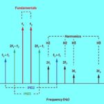
Sinusoidal inputs applied to a nonlinear system produce an output containing different frequencies, and the results can be good, bad, or ugly.
According to the dictionary definition, intermodulation is “the production in an electrical device of currents having frequencies equal to the sums and differences of frequencies supplied to the device.” In the literature of electrical engineering, the word is often followed by the word distortion. Indeed, intermodulation distortion (IMD) is bad — a problem to eliminate. However, the process that causes IMD is often put to good use in communications and test applications.
What’s an example of a good use?
Frequency translation — upconversion or downconversion. Upconversion translates a baseband or intermediate-frequency (IF) signal into an RF signal for transmission; it finds use in arbitrary waveform generators. Downconversion translates a received RF signal into a baseband or IF signal; it finds use in high-frequency signal analyzers.
How long has frequency translation been in use?
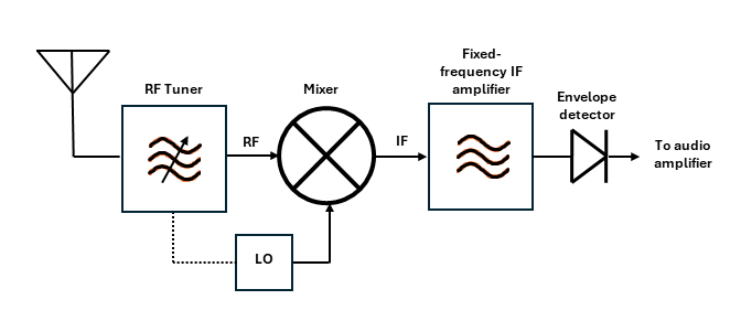
At least since back to the time of the telegraph. Figure 1 shows a simplified diagram of a superheterodyne amplitude modulation (AM) radio. Here, a mixer downconverts an RF signal to a fixed intermediate frequency (IF) with the help of a variable local oscillator (LO) coupled to an RF tuner. This circuit was patented in 1917 and is still in use today.
What about the bad part — is IMD worse than harmonic distortion?
In the audio field, IMD is generally considered worse. Composers have been writing harmonics into their music for centuries. If you listen to a composition, you haven’t heard before and don’t have a copy of the score, you might not know whether you’re hearing harmonic distortion or an intentionally written harmonic line. On the other hand, listeners perceive IMD as ugly. (There are exceptions.) But in general, distortion is distortion, whether harmonic or IMD, and it should be minimized. Even in the audio field, composers don’t want you to hear harmonics they didn’t intend.
OK, back to frequency translation: how does a mixer work?
A mixer is a nonlinear component that multiplies two sinusoidal inputs and generates an output containing the sum and differences of the input frequencies.
Wait, remind me, why is multiplication nonlinear?
Multiplication is not inherently nonlinear. Multiplication of a variable and a constant is a simple linear gain stage. The multiplication of two variables is nonlinear.
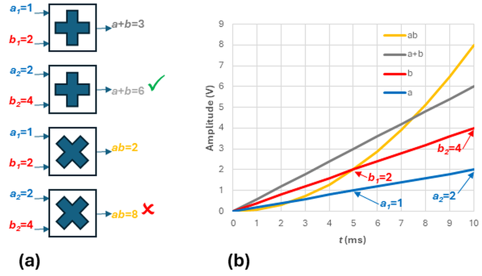
The test for linearity is whether a system adheres to the superposition principle, which in turn requires that the system exhibit additivity and homogeneity. Additivity says that if input a produces output x and input b produces output y, then simultaneously applying a+b will produce x+y.
Mathematically, homogeneity conforms to f(cx)=cf(x), where c is a constant. In short, homogeneity says that if you double the input, the output will double.
Figure 2 tests two systems for homogeneity: an adder and a multiplier, each of which takes two variables as inputs. As shown in Figure 2a, doubling the adder’s inputs doubles the outputs, earning a check mark for homogeneity. For the multiplier, doubling the inputs more than doubles the output, so the multiplier fails the homogeneity test. Figure 2b shows the results graphically. To your earlier point on multiplication, the red line is the blue line multiplied by the constant 2, and the result is linear.
Could you provide a specific mixer example?
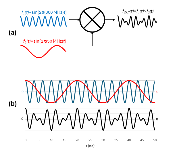
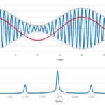
Figure 3a shows a mixer multiplying 300-MHz and 50-MHz signals. Figure 3b provides a closer look at the inputs (red and blue traces) and output (black trace).
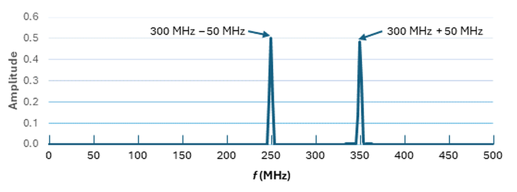
The black trace’s frequency content is not immediately apparent, so we’ll borrow the fast Fourier transform (FFT) from our previous series on the subject (part 4 includes a summary of the entire series) and take a closer look. Figure 4 shows that the mixer has replaced the 50-MHz and 300-MHz input signals with signals representing those signals’ sum (350 MHz) and difference (250 MHz).
Wait, what happens if we modulate a carrier? Your example suggests the carrier frequency disappears, to be replaced by other frequencies. That doesn’t seem to be what happens in the real world.
It depends on the modulation type. We will take a closer look at part 2. Then we’ll focus on IMD (including its subset passive IMD, or PIM distortion), how to measure it, and how to minimize it.


Leave a Reply
You must be logged in to post a comment.