• Skip to primary navigation
  • Skip to main content
  • Skip to primary sidebar
  • Skip to footer
  • Advertise
  • Subscribe

Test & Measurement Tips

Oscilloscopes, electronics engineering industry news, how-to EE articles and electronics resources

  • Oscilloscopes
    • Analog Oscilloscope
    • Digital Oscilloscope
    • Handheld Oscilloscope
    • Mixed-signal Oscilloscope
    • PC-based Oscilloscopes – PCO
  • Design
  • Calibration
  • Meters & Testers
  • Test Equipment
  • Learn
    • eBooks/Tech Tips
    • FAQs
    • EE Training Days
    • Learning Center
    • Tech Toolboxes
    • Webinars & Digital Events
  • Video
    • EE Videos
    • Teardown Videos
  • Resources
    • Design Guide Library
    • Digital Issues
    • Engineering Diversity & Inclusion
    • Leap Awards
    • White Papers
  • Subscribe
You are here: Home / Featured / What is intermodulation, and is it good or bad? Part 2

What is intermodulation, and is it good or bad? Part 2

April 17, 2024 By Rick Nelson Leave a Comment

A mixer can upconvert and downconvert a modulated signal with no loss of baseband information.

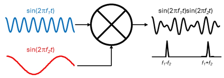
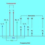
Part 1 of this series described intermodulation resulting from the combining of two or more sinusoidal signals through a nonlinear device such as the mixer in Figure 1. The mixer’s output is the product of its two inputs, and its output’s frequency content is f­1+f2 and f­1–f2. The frequencies f­1 and f2 do not appear in the output (unless it is f­1=f2, in which case the output contains f­1=f2 plus a DC component).

Figure 1. A mixer’s output includes the sum and difference of its input waveforms’ frequencies.

That brings up the question: if f1 in Figure 1 is a carrier and f2 is a message signal that we want to use to modulate the carrier, does the carrier disappear during the modulation process?
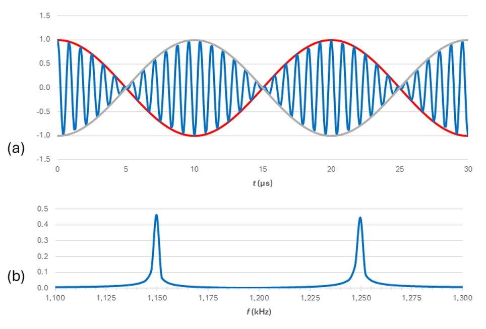
It depends on the modulation scheme. Here is the equation for a version of amplitude modulation (AM) called double-sideband suppressed-carrier (DSBSC) modulation:

Here,  fM is the message signal we want to use to modulate the carrier fC. Figure 2a shows the modulated waveform (blue) for fC equals 1,200 kHz and fM equals 50 kHz (red, with the gray curve representing negative fM). Figure 2b shows the fast Fourier transform (FFT) of the modulated signal. Here, the original 1,200-kHz carrier doesn’t appear—only the sidebands at 1,150 kHz and 1,250 kHz—that is, ±50 kHz from 1,200 kHz.

Figure 2. The DSBSC signal (a) includes sidebands, but the original 1,200-kHz carrier signal doesn’t appear.

What about conventional AM without the suppressed carrier?
Here’s the relevant equation:

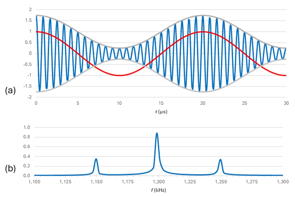
Figure 3a shows the time-domain representation of fAM(t) for the same frequencies used in Figure 2. Note that in the conventional AM equation, the term to the immediate right of the equals sign isn’t multiplied by any other variable. Also note that in Figure 3a, the absolute value of the carrier-envelope (gray) is always greater than zero. Figure 3b shows the FFT. Here, the carrier does appear explicitly, with the sidebands offset by ±50 kHz.

Figure 3. The time-domain representation of a conventional AM signal (a) yields an FFT (b) that includes the original carrier.

What’s another good use for intermodulation?
Say we don’t want to use the 1,200-kHz carrier in Figure 3. Intermodulation lets us translate the carrier and its accompanying sidebands to other frequencies. For example, Figure 4a shows the modulated carrier from Figure 3a (blue) and a 900-kHz cosine wave (red). Figure 4b shows the product of those two waveforms (obtained by combining them in a mixer).

Figure 4. Combining the Figure 3 modulated blue waveform and 900-kHz red waveform (a) in a mixer results in the waveform representing the product (b).

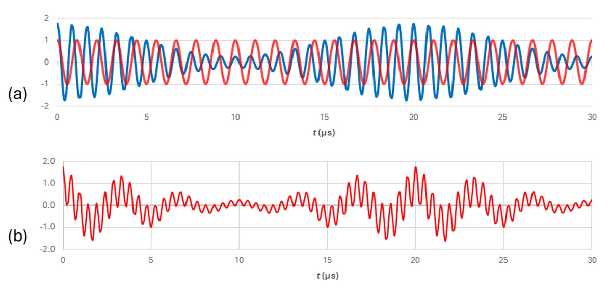
Figure 5 shows the FFT of the Figure 4b waveform. Note that the 1,200-kHz carrier and its sidebands have disappeared; I’m showing them as a dotted blue trace for reference. The 1,200-kHz carrier has been downconverted by 900 kHz to 300 kHz and upconverted by 900 kHz to 2,100 kHz, with the sidebands maintaining their ±50-kHz offset from each carrier, as emphasized in the insets. The key point here is that the frequency-translation process does not interfere with our ability to retrieve our original baseband message.

Figure 5. The FFT of the Figure 4b waveform shows that the Figure 3b carrier and its sidebands have been downconverted and upconverted by 900 kHz.

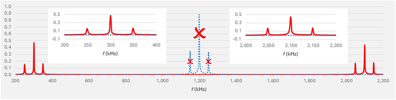
Don’t 50-kHz sidebands seem unusual for AM?
Yes. Typical AM would be better represented by 5-kHz sidebands on carriers from about 560 to 1,700 kHz, and the sidebands wouldn’t be peaks but rather approximations of continuous functions that taper off near the sideband limits. I chose the parameters here to enable both the downconverted and upconverted carriers in Figure 5 to appear on the same chart with sufficient resolution so that the sidebands would still be clearly visible. To produce the FFTs in this post, I used Microsoft Excel, as described in a recent series. In part 3, we’ll take a quick look at the reasons for choosing the parameters and settings I used. That will conclude our look at the good uses of intermodulation, and we’ll turn our focus on the bad: intermodulation distortion (IMD).

You may also like:


  • What is intermodulation, and is it good or bad? Part…

  • How to locate EMI emissions with near-field probes: Part 3

  • The difference between electronic distortion and noise
  • amplifiers
    Choosing the right amplifier

  • The difference between noise and jitter

Filed Under: Communication Test, FAQ, Featured, wireless Tagged With: FAQ

Reader Interactions

Leave a Reply Cancel reply

You must be logged in to post a comment.

Primary Sidebar

Featured Contributions

Why engineers need IC ESD and TLP data

Verify, test, and troubleshoot 5G Wi-Fi FWA gateways

How to build and manage a top-notch test team

How to use remote sensing for DC programmable power supplies

The factors of accurate measurements

More Featured Contributions

EE TECH TOOLBOX

“ee
Tech Toolbox: 5G Technology
This Tech Toolbox covers the basics of 5G technology plus a story about how engineers designed and built a prototype DSL router mostly from old cellphone parts. Download this first 5G/wired/wireless communications Tech Toolbox to learn more!

EE TRAINING CENTER

EE Learning Center

EE ENGINEERING TRAINING DAYS

engineering
“test
EXPAND YOUR KNOWLEDGE AND STAY CONNECTED
Get the latest info on technologies, tools and strategies for EE professionals.
“bills

RSS Current EDABoard.com discussions

  • Why need use TOPmetal Stacking?
  • Monte-Carlo simulation error on ADE-XL
  • Snooping Around is All
  • Identification of a 6 pin smd chip (sto-23-6) marked E2
  • Dynacord enter protect

RSS Current Electro-Tech-Online.com Discussions

  • Does US electric code allow branching ?
  • Fun with AI and swordfish basic
  • using a RTC in SF basic
  • Faulty heat air gun (dc motor) - problem to locate fault due to Intermittent fault
  • Sump pit water alarm - Kicad 9
Search Millions of Parts from Thousands of Suppliers.

Search Now!
design fast globle

Footer

EE World Online Network

  • 5G Technology World
  • EE World Online
  • Engineers Garage
  • Analog IC Tips
  • Battery Power Tips
  • Connector Tips
  • DesignFast
  • EDA Board Forums
  • Electro Tech Online Forums
  • EV Engineering
  • Microcontroller Tips
  • Power Electronic Tips
  • Sensor Tips

Test & Measurement Tips

  • Subscribe to our newsletter
  • Advertise with us
  • Contact us
  • About us

Copyright © 2025 · WTWH Media LLC and its licensors. All rights reserved.
The material on this site may not be reproduced, distributed, transmitted, cached or otherwise used, except with the prior written permission of WTWH Media.

Privacy Policy