The phrase and concept “orthogonal” is widely used in engineering, but it is also often misunderstood.
I was chatting the other day with a non-technical friend and said something like, “Oh, that won’t happen. Those two things are orthogonal.” My friend looked at me and replied with a “huh?” and he was right to do so.
Why? Because the term “orthogonal” (from Latin orthogonius or “right-angled”) and the concept behind it is used in many engineering disciplines, but it’s not an everyday conversation term. The same caution applies to its sibling term “quadrature,” also widely used in engineering, especially signal theory, signal processing, and communication coding and channels.
This article will look at various aspects of orthogonal and its implications for engineering analysis. We’ll begin with an almost intuitive mechanical orthogonal situation, look at the math behind the meaning of orthogonal, and conclude with the electronic version, which is often called out as “quadrature.”
Is “orthogonal” the same as “uncorrelated?” The answer is “yes, no, and maybe” and has many perspectives beyond what we can cover here. In brief, “orthogonal” is a mathematical relationship between a continuous signal or process, while “uncorrelated” is a statistical relationship. But the story is more complicated and confusing than that; the References link to some interesting discussions on the question. However, in common conversation, the two terms are often somewhat synonymous.
Start with mechanical forces
One of the first lessons in basic mechanical engineering is that a force at an arbitrary angle can be resolved into two orthogonal components – meaning they are at right angles to each other – to a selected frame of reference. (If the system has gravity pulling down, as it often does, the frame of reference is usually aligned with horizontal and vertical directions. It’s easiest to start with a mechanical example since it is somewhat intuitive and familiar to most people).
Consider a 400-newton (N) force that is being exerted at a 60⁰ angle to move a railroad car eastward (to the right) along a railroad track (Figure 1). The force applied to the car has both an up/down (southward) and a left/right component (eastward), with respect to the selected frame of reference. Of course, this is a two-dimensional example; in the real world, we have three axes – x, y, and z at right angles to each other. Using two dimensions simplifies the discussion and makes examples easier to follow.
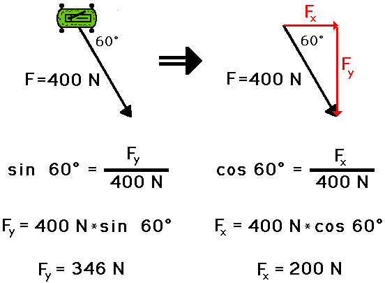
The sine and cosine functions are used to determine the magnitudes of these two components, along with a basic diagram with a labeled angle and a labeled hypotenuse. The sine function calculates the southward component and the cosine function determines the eastward component.
This is all fairly basic stuff. But there’s still some insight to be gained from this: No amount of force in the up/down direction can impact the force in the left/right direction, and vice versa. That’s because the sine of 0⁰ is zero, as is the cosine of 90⁰.
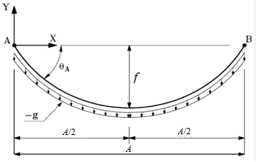
This independence between the resolved forces has a very practical implication. Suppose you have a rope or wire stretched between two supports, and you want to pull the wire taut and make it absolutely, perfectly horizontal, a fairly common goal. To make the analysis easier, consider the rope to be weightless. Still, it has a weight attached to and suspended from its center (if the suspended weight is much heavier than the rope, this is a very valid simplification) (Figure 2). So, how hard do you have to pull horizontally on the rope to make it go truly, absolutely straight across?

The answer is easy: you need an infinite force! As you pull horizontally more and more, less and less of that force component is available to lift the weight vertically as the two forces become closer to being at right angles (orthogonal) to each other. It’s the classic asymptote problem: you can get closer and closer, but you can never get there.
In fact, as you get closer to the desired truly horizontal angle, each unit of force along the angle of the rope yields less and less force in the vertical direction. In short: a force vector has no influence at 90⁰ to its line of action, but you can get as close as you want even if you can’t get there completely.
If you think ignoring the rope’s weight is a “cheat” to skew or mislead the discussion, no, it’s not. Using the rope’s weight having a uniform load per unit length pulling down on it, with or without a suspended weight, is the classic “catenary” problem and was solved hundreds of years ago (Figure 3). However, the complete solution requires using the hyperbolic trigonometry functions (sinh and cosh) rather than the more-common sines and cosines. The simplification is more informative for illuminating the basic orthogonal reality.
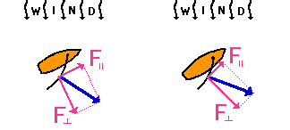
Resolving a force into its orthogonal components shows why a sailboard cannot sail directly into the wind but can sail against the wind by tacking at an angle. When a boat heads directly into the wind, there is no component of force in the direction that the sailboat is heading.
However, if the boat heads at an angle into the wind, then the wind force can be resolved into two components (Figure 4), and the component of force in the direction parallel to the sailboat’s heading will push the boat at an angle into the wind. Typically, when tacking into the wind, a sailboat will travel at a cycle of about ±45-degree angles with respect to the wind’s direction (other factors such as water current affect the actual preferred setting). Note that the sail is usually not aligned with the sailboat’s hull, and the angle between the two affects the resolution of forces.
Part 2 looks at the issue of orthogonality with respect to its formal definition and its application to communications and signal theory.
EE World Related Content
The basics of 5G’s modulation, OFDM
Is Li-Fi “To Be” or “Not To Be”? Part 2 – Attributes
Reaction wheels ensure satellites maintain the right attitude: Part 1What does an eye diagram, or eye pattern on an oscilloscope mean?
Basics of eye diagrams
Eye and Constellation Diagrams, Pt 2
Eye and Constellation Diagrams, Pt 1
Electric locomotives and catenary power systems – Part 3: power delivery
Generating sine waves from triangle waves
Additional References
Orthogonality
- Physics Classroom, “Forces in Two Dimensions”
- Stack Exchange, “When are two signals orthogonal?”
- Wikipedia, “Orthogonality”
- All About Circuits, “Orthogonal signals”
- Math Reference, “Fourier Transforms, Sines and Cosines are Orthogonal”
- Math Stack Exchange, “What does it mean when two functions are “orthogonal”, why is it important?”
- MIT, “Orthogonal Functions and Fourier Series”
- University of California/Berkeley, “Orthogonal Signaling”
- MIT, “Analog and Digital I/Q Modulation”
- Princeton University, “From AM Radio to Digital I/Q Modulation”
- Tektronix, “What’s Your IQ – About Quadrature Signals”
- NuWaves Engineering, “Application Note AN-005: Understanding Constellation Diagrams and How
They Are Used” - com, “What is a Constellation Diagram?”
- Keysight Technologies, “Concepts of Orthogonal Frequency Division Multiplexing (OFDM) and 802.11 WLAN”
Orthogonal versus uncorrelated: issues
- Stack Exchange, “What is the relationship between orthogonal, correlation and independence?”
- Statistics How To, “What is Orthogonality in Statistics?”
- GitHub, “Orthogonality Does Not Imply Uncorrelated-Ness or Independence”
- Brereton, R. G., Journal of Chemometrics, “Orthogonality, uncorrelatedness, and linear independence of vectors”



Leave a Reply
You must be logged in to post a comment.